background image

Instruction Manual

For the 

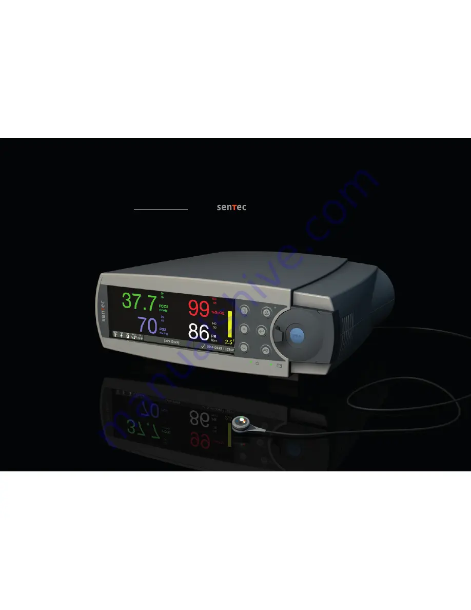
 Digital Monitoring System

(Software version SMB SW-V08.02; MPB SW-V06.02)

Summary of Contents for SpO2

Page 1: ...Instruction Manual For the Digital Monitoring System Software version SMB SW V08 02 MPB SW V06 02 ...

Page 2: ...SenTec Digital Monitoring System Noninvasive Ventilation and Oxygenation Monitoring John Smith Sarah Miller ...

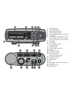
Page 3: ...ellow LED 6 Door Handle 7 Docking Station Door colored dot in center of door indicates the SDM s PO2 activation status blue if activated orange otherwise 8 Enter Button 9 Display Button 10 AC Power Battery Indicator green yellow LED 11 UP DOWN Buttons 12 ON OFF Indicator green LED 13 Status Bar 14 Speaker on the side 15 Sensor Connection Port 16 Multipurpose l O Port Nurse Call Analog Output 17 Se...

Page 4: ...ician Patents Trademarks Copyright International Industrial Design No DM 054179 Japanese Design No 1137696 U S Design Patent No D483488 Canadian Patent No 2466105 European Patent No 1335666 German Patent No 50111822 5 08 Spanish Patent No 2278818 Hongkong Patent No HK1059553 U S Patent No 6760610 Chinese Patent No ZL02829715 6 European Patent No 1535055 German Patent No 50213115 2 Spanish Patent N...

Page 5: ...ion Disconnection of Digital Sensor Adapter Cable 13 Connection of a SenTec TC Sensor 14 Sensor Check Sensor Calibration Storage and Membrane Change 15 Checking a SenTec TC Sensor 15 Sensor Calibration and Storage 16 Changing the Sensor Membrane 17 Patient Monitoring with the SDMS 20 Selection of Patient Type Measurement Site and Sensor Attachment Accessory 20 Check SDM Settings and System Readine...

Page 6: ...icators Signals 45 Alarms 46 Status Bar with Status Icons and Status Messages 48 Maintenance of the SDMS 50 Routine Checks 50 Service 51 Specifications of tcPCO2 tcPO2 and Pulse Oximetry 52 Specifications of tcPCO2 and tcPO2 52 Specifications of Pulse Oximetry 53 Glossary of Symbols 54 ...

Page 7: ...ion and Limitations Transcutaneous PCO2 and PO2 Principles of Operations of tcPCO2 and tcPO2 Carbon dioxide CO2 and Oxygen O2 are gases that readily diffuse through body and skin tissue and therefore can be measured by an adequate noninvasive sensor being applied at the skin surface If the skin tissue beneath the sensor site is warmed up to a constant temperature local capillary blood flow increas...

Page 8: ...vasoconstrictions low blood pressure or circulatory centralization shock Please refer to Technical Manual for the SDM HB 005752 and the references cited therein for additional information on transcutaneous blood gas monitoring Limitations of tcPCO2 and tcPO2 The following clinical situations or factors may limit the correlation between transcutaneous and arterial blood gas tensions Hypo perfused s...

Page 9: ... reference barometer Pulse Oximetry Principles of Operations of Pulse Oximetry The SDMS uses pulse oximetry to measure functional oxygen saturation SpO2 and pulse rate PR Pulse oximetry is based on two principles firstly oxyhemoglobin and deoxyhemoglobin differ in their absorption of red and infrared light spectrophotometry and secondly the volume of arterial blood in tissue and hence light absorp...

Page 10: ...lse Oximetry The following clinical situations or factors may limit the correlation between functional oxygen saturation SpO2 and arterial oxygen saturation SaO2 and may cause the loss of the pulse signal dysfunctional hemoglobins COHb MetHb anemia intravascular dyes such as indocyanine green or methylene blue low perfusion at the measurement site e g caused by inflated blood pressure cuff severe ...

Page 11: ...hanger the membrane and electrolyte can be changed with the ease of 4 identical Press and Turn steps in a highly reproducible manner p 17 Calibration of the PCO2 segment of SenTec TC Sensors is recommended every 6 to 12 hours and mandatory every 12 to 16 hours p 16 The PO2 measurement of the OxiVenT Sensor is virtually drift free and hence calibration free Nevertheless the SDM as a precaution cali...

Page 12: ...ensor Digital Sensor Adapter Cable to connect a SenTec TC Sensor to SDM Ear Clip and Multi Site Attachment Rings to attach SenTec TC Sensors to patients Staysite Adhesive to improve attachment of Multi Site Attachment Rings e g in high humidity environments for patients who perspire profusely and or in challenging patient motion conditions Contact Gel contact liquid for the application of SenTec T...

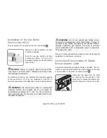
Page 13: ...rovided in the SDMS Service Manual HB 005615 To ensure proper operation of the SDMS precisely follow the instructions provided in this Instruction Manual step by step WARNING The instructions given in the SDMS Quick Reference Guide the SDMS Instruction Manual the Technical Manual for the SDM and on the SDMS Manual CD must be followed in order to ensure proper instrument performance and to avoid el...

Page 14: ...a LED backlight display a new fully charged battery will provide up to 10 hours of monitoring time if Sleep Mode OFF or Auto and up to 12 hours of monitoring time if Sleep Mode ON It takes approximately 7 hours to fully charge a drained battery The AC Power Battery Indicator 10 provides information on the charging status of the battery Green SDM connected to AC power battery fully charged Yellow S...

Page 15: ...ot expose to temperatures exceeding 50 C 122 F Do not pierce or burn even after use Do not spray on a naked flame or any incandescent material WARNING Do not use expired gas bottles or gas bottles from manufacturers other than SenTec The use of non SenTec gas bottles may damage the Docking Station Improper calibration gas mixtures will result in incorrect sensor calibrations and subsequently resul...

Page 16: ...essage Calibrate sensor for exceptions see description of the feature SMART CALMEM p 17 Insert the sensor into the Docking Station for sensor calibration p 16 If the sensor s Membrane Change Interval has elapsed this usually applies to new sensors the SDM will trigger the message Change sensor membrane upon insertion of the sensor into the Docking Station In this case you must change the sensor me...

Page 17: ...CAUTION Do not touch the delicate optical glass components embedded in the sensor s surface should the membrane be missing b Do not use the sensor if there is any visible damage to the sensor housing or cable if the color of the ring around the glass electrode has a metallic luster should be brown or if the sensor s red LED does not light when the sensor is connected to the SDM Instead contact qua...

Page 18: ...librations that are activated with the menu function Calibrate sensor Sensor Calibration and Storage If a sensor calibration is mandatory the SDM displays the message Calibrate sensor a low priority alarm sounds and PCO2 and PO2 are marked as invalid values replaced by Good to know Calibration Intervals for SenTec TC Sensors can last up to 12 hours Once the Calibration Interval has elapsed sensor ...

Page 19: ...ART CALMEM reduces the number of required calibrations and hence the consumption of calibration gas Changing the Sensor Membrane The membrane of a SenTec TC Sensor must be changed if the Membrane Change Interval has elapsed In this case the SDM displays the message Change sensor membrane triggers a low priority alarm marks PCO2 PO2 as invalid and activates the menu Membrane Change provided the sen...

Page 20: ... sensor is inside in the Membrane Changer nor pick up the Membrane Changer as this may lead to dislodging the sensor from the Membrane Changer Four Press and Turn Steps to Change the Membrane The membrane change procedure consists of four identical press and turn steps To provide better guidance these steps are marked with the corresponding numbers on the Membrane Changer Step 1 removes the old se...

Page 21: ...ec 1 1 1 1 Removing Sensor from Membrane Changer Press once again or lift the sensor to release and remove the sensor from the Membrane Changer Inspecting Sensor Membrane Check the condition of the sensor membrane and the integrity of the sensor p 15 Repeat the membrane change if nec essary Do not use the sensor if any problems are noted Confirming Membrane Change on SDM Once the inspection of the...

Page 22: ...with the SDMS Selection of Patient Type Measurement Site and Sensor Attachment Accessory Adult if Older than Term Birth 1 Month Earlobe Use Ear Clip for mature intact skin All other sites Use MAR e MI for mature intact skin or MAR e SF for sensitive fragile skin Selection of Sensor Attachment Accessory PCO2 PCO2 SpO2 PR Neonatal if Younger than Term Birth 1 Month PCO2 PO2 application area applicat...

Page 23: ...has multiple piercings consider using a Multi Site Attachment Ring model MAR e MI or model MAR e SF to attach the sensor to an alternate site p 24 Note If more secure sensor attachment is required e g in high humidity environments for patients who perspire profusely and or in challenging patient motion conditions the Staysite Adhesive model SA MAR can be used complementary with the Multi Site Atta...

Page 24: ...6 7 Note Pressing the Enter Button p 42 while the Ready for use screen displays activates a Quick Access Menu with the possibility to activate additional calibrations p 16 to access the sub menu Profiles or to activate the V Check Mode p 35 The following information is displayed in the upper area of the Ready for use Calibration screen 1 Patient Type Indicator yellow Displays the current patient t...

Page 25: ...ure Displays the currently selected sensor temperature this indicator is only displayed if the connected sensor is heated WARNING The use of temperatures higher than 41 C requires special attention to patients with susceptible skin e g neonates geriatric patients burn victims patients with skin diseases 6 Special Temperature Settings Split arrow indicating the current configuration of INITIAL HEAT...

Page 26: ...ulti Site Attachment Ring Easy According to the procedure described point by point below a Multi Site Attachment Ring MAR or Multi Site Attachment Ring Easy MARe is first attached to the measurement site one small drop of contact liquid is then applied to the center of the sensor and finally the sensor is snapped into the ring Alternatively you may also click the sensor into the ring first remove ...

Page 27: ... Do not use the sensor if any problems are noted 8 Apply one small drop of contact liquid to the center of the sensor surface Ensure to keep the sensor horizontal membrane pointing upwards so that the contact liquid does not run off the membrane Flip over the sensor just before inserting it into the ring Note As contact liquid you may use SenTec s Contact Gel clean tap water sterile water or steri...

Page 28: ...to the cheek or another applicable site For other application sites tape the cable to the skin at a distance of 5 to 10 cm from the sensor head Route the sensor cable properly to avoid entanglement or strangulation and secure it with a Clothing Clip to an appropriate site of the patient s clothing or bed linen Ensure that the sensor cable is loose enough for not to be stretched during monitoring G...

Page 29: ...e g by using a pressure bandage may cause pressure ischemia at the measurement site and consequently inaccurate measurements necrosis or in combination with heated sensors burns 1 Check current SDM Settings SDM Profile and verify system readiness message Ready for use p 22 Change SDM Settings SDM Profile if necessary 2 Clean the earlobe with a swab wetted with 70 isopropanol or according to your i...

Page 30: ...overed by the earlobe Ensure that air gaps are eliminated between the skin and the sensor 5 Open the Docking Station Door and remove the sensor Note Always grab the sensor at its neck to avoid pulling and tearing the sensor cable 6 Close the Docking Station Door 7 Check the condition of the sensor membrane and the integrity of the sensor p 15 Change the membrane if necessary p 17 Do not use the se...

Page 31: ...ient see previ ous sections the SDM usually detects that the sensor was put on the patient and initiates monitoring for the enabled parameters If the sensor is applied on a site approved for SpO2 PR monitoring p 20 Sensor On Patient is typical ly detected within a few seconds otherwise within less than 2 minutes When obtaining an adequate patient signal is difficult it may be possible that the SDM...

Page 32: ...2 and PR usually stabilize within a few seconds whereas PCO2 typically increases and PO2 typically decreases to reach a stabilized value within 2 to 10 minutes see below TC Stabilization after Sensor Application or TC Artifacts A good hermetically sealed contact between the TC Sensor and the skin provided TC readings typically stabilize within 2 to 10 minutes after sensor application i e the time ...

Page 33: ...on may cause TC Artifacts In such cases try to keep the patient still or change the sensor to a site involving less motion Preconfigured Measurement Screens The SDM s numeric values and online trends provide continuous monitoring of the enabled parameters Depending on the sensor type the selected patient type and the enabled parameters different sets of preconfigured measurement screens are availa...

Page 34: ...rameters and the x values and baseline values derived thereof by assessing the severity of conditions presented to the SDM The results of this evaluation are used to display status messages and or quality indicators for the different parameters While a parameter is marked as Valid Alarm surveillance for the respective parameter if applicable is active and the SDM displays the parameter in the sele...

Page 35: ...icate that the current PCO2 reading is 10 1 mmHg higher than the baseline of 33 3 mmHg which was set 12 minutes ago Good to know To assess the possible impact of a change in patient treat ment e g changing ventilator settings administration of drugs such as sedatives or opioids changing supply of supplemental oxygen etc on the patient s ventilation and or oxygenation it is recommended to set a bas...

Page 36: ...pisodes during which the sensor required less more power to maintain the sensor temperature than the AHP reference value At constant ambient temperature consequently RHP values below above the center line may indicate episodes with a decreased increased local skin blood flow beneath the sensor site Keeping in mind the possible influence of local skin blood flow fluctuations on transcutaneous blood...

Page 37: ...tivates displaying the above mentioned statistical results for the data assessed during the V Check Measurement Phase The V Check Re sults Screen remains displayed until the Menu or Display But ton are pressed or another V Check Measurement is started Note The V Check Mode Indicator appears on the Ready for use and Calibration screen p 22 if the V Check Mode is ON On measurement screens p 31 the V...

Page 38: ...splayed adjacent to the PCO2 label IC xx x if mmHg IC x xx if kPa where xx x x xx is the current offset respectively if additionally a fixed Severinghaus Correction is used the PCO2 In vivo Correction offset is marked with an asterisk e g IC x xx WARNING A PCO2 In Vivo Correction should only be enabled by personnel understanding the principles and limitations of transcutaneous PCO2 monitoring p 6 ...

Page 39: ...rm surveillance of multiple SDMs connected to the same network as the PC is possible Operator Events Baselines and certain SDM settings can be set controlled remotely on the included SDMs Furthermore download of SDM Trend Data is simultaneously possible for multiple SDMs Remaining Monitoring Time Site Time Elapsed Alarm During monitoring the Remaining Monitoring Time Icon p 48 continuously indicat...

Page 40: ...g Station Door the red light will appear Close the Docking Station Door Sensor Removal with Multi Site Attachment Ring Easy Remove the sensor from the patient when monitoring is completed or monitoring time has elapsed message Site time elapsed or Calibrate sensor CAUTION For site inspection and or calibration the Multi Site Attachment Ring Easy can remain on the same site for up to 24 hours and m...

Page 41: ...ly one small drop of contact liquid to the site before reinserting the sensor into the MAR e Sensor Removal without Reattachment to Same Site 1 Remove the sensor together with the Multi Site Attachment Ring Easy by carefully lifting the ring s little tab 2 Clean the skin with a dry swab or if necessary a swab with 70 isopropanol or according to your institution s skin cleaning degreasing procedure...

Page 42: ...a swab wetted with 70 isopropanol to remove any contact liquid residues or dirt for other approved cleaning agents refer to the sensor s Directions for Use 4 Check the condition of the sensor membrane and the integrity of the sensor p 15 Change the membrane if necessary p 17 Do not use the sensor if any problems are noted Important Before reapplying the sensor to the same earlobe we recommend cali...

Page 43: ...ll drop of contact liquid to the sensor s center before reinserting it into the Ear Clip Sensor Removal without Reattachment to Same Earlobe 1 Open the clip s jaws and remove it from the earlobe together with the sen sor by turning it sideways 2 Clean the earlobe with a dry swab or if necessary a swab wetted with 70 isopropanol or according to your institution s skin cleaning degreasing procedures...

Page 44: ...nges become effective immediately without confirmation see example 1 below For parameters that are highlighted with a yellow menu bar in editing mode changes Menu Previous Level Button to activate the menu to return to the menu on the next higher level only if editing mode is inactive exits the menu if pressed while at top level to deactivate editing mode for the selected menu parameter Note Menu ...

Page 45: ...t changes become effective immediately Press or to deactivate editing mode for the parameter SpO2 Low Limit Note that the Enter symbol reappears at the end of the line and that the color of the menu bar remains blue Press to return to the main menu or to exit the menu Note Changes made with the UP Down Buttons immedi ately become effective without confirmation for all parameters except Patient Ena...

Page 46: ...ter a successful membrane change the membrane change must be confirmed on the SDM by using the function Membrane Change Done in the menu Membrane Change To confirm a membrane change proceed as follows Press to access the menu Press twice to scroll down the blue menu bar to the menu Membrane Change Press to open activate the menu Membrane Change Note The SDM automatically activates the menu Membran...

Page 47: ...tution its volume is not adjustable The Key Click short tone indicates that a button has been properly pressed use the parameter Key Click to switch off adjust the volume of this signal LED Indicators The following visual LED indicators are located on the front panel of the SDM AUDIO PAUSED AUDIO OFF Indicator Yellow LED Auditory alarm signals paused for 1 or 2 minutes Yellow LED flashes Auditory ...

Page 48: ... user when a physiological measurement parameter PCO2 PO2 SpO2 PR violates its alarm limits and to inform the user about technical conditions of the equipment that require operator response or awareness By degree of urgency the SDM s alarm conditions are assigned to the following priorities High priority SpO2 limit violation medium priority PCO2 PO2 or PR limit violation Battery Critical if SDM no...

Page 49: ...the patient s safety could be compromised Auditory Alarm Signals The SDM s auditory alarm signals are priority encoded A high priority alarm condition is indicated by a high pitched fast pulsing tone two bursts of five short pulses repeated every 10 seconds a medium priority alarm condition by a medium pitched pulsing tone one burst of three pulses repeated every 10 seconds and a low priority alar...

Page 50: ...areNeT Central Station is interrupted For details refer to the Technical Manual for the SDM HB 005752 Status Bar with Status Icons and Status Messages The Status Bar is located in the bottom of nearly all screens 1 2 3 4 5 6 7 8 9 On the left it displays up to 5 Status Icons 1 to 5 The Battery Icon 1 indicates the remaining battery capacity in The icon highlights yellow when battery capacity is be...

Page 51: ...onize the date time setting of the SDM and the PC The Sensor Temperature Icon 4 indicates the measured sensor temperature C and the current setting of SITE PROTECTION A red blue rightward arrow with tip down appears if SITE PROTECTION is ON a red rightward arrow if it is OFF The Sensor Temperature Icon is marked yellow during INITIAL HEATING blue if SITE PROTECTION has reduced the sensor temperatu...

Page 52: ...your SDM is permanently switched on switch it off and on again once a month to perform a POST Weekly clean the Docking Station gasket using a cotton swab moistened with 70 isopropanol for other approved cleaning agents refer to the Technical Manual for the SDM Monthly inspect the Docking Station Door and gasket for mechanical and functional damages Monthly check the SDM sensors sensor adapter cabl...

Page 53: ...gulations refer to the Service Manual for the SDMS for details To perform a safety check and for service or repair contact qualified service personnel or your local SenTec representative Please note that repair and service procedures which require opening the cover of the SDM must be performed by SenTec authorized service personnel WARNING The cover should only be removed by SenTec authorized serv...

Page 54: ...ct detection After sensor application or occur rence of a tcPCO2 artifact tcPCO2 is displayed in grey until it re stabilizes tcPO2 Measurement range 0 800 mmHg 0 106 7 kPa Resolution 1 mmHg 0 1 kPa Drift Typically 0 1 hour Response time T90 Typically 150 sec Linearity Typically 1 mmHg 0 13 kPa Interferences by anesthetic gases Negligible Stabilization artifact detection After sensor application or...

Page 55: ... adult volunteers over the specified saturation range by applying a defined sensor type to the specified measurement sites Pulse oximeter SpO2 readings were compared to SaO2 values of blood samples measured by hemoximetry SpO2 accuracy is expressed as Arms root mean square The indicated variation equals plus or minus one standard deviation 1SD which encompasses 68 of the population Note A function...

Page 56: ... temperature limits to which the medical device can be safely exposed upper and lower limits of temperature are indicated adjacent to the upper and lower horizontal lines Humidity limitation Indicates the range of humidity to which the medical device can be safely exposed humidity limitation indicated adjacent to the upper and lower horizontal lines Do not re use Single use Indicates a medical dev...

Page 57: ...irective 93 42 EEC June 1993 If applicable the 4 digit Notified Body number is added near or below the CE symbol Caution Refer to accompanying documents for further details UL Label Declaration of conformity of the equipment WEEE Disposal European consumers are obliged by law to dispose Waste Electrical and Electronic Equipment WEEE according to the WEEE Directive 2002 96 EC 1 All electrical and e...

Page 58: ...tly switched off by setting menu parameter Alarm to OFF On Off Indicator On SDM front panel LED green SDM turned ON LED off SDM turned OFF AC Power Battery Indicator On SDM front panel LED green Connected to AC power battery fully charged LED yellow Connected to AC power battery charging LED off Not connected to AC power i e powered by internal battery Note The AC Power Battery Indicator functions...

Page 59: ......

Page 60: ...ADVANCING NONINVASIVE PATIENT MONITORING HB 005771 l Art 100978 Date of release 10 2018 ...

Reviews: