www.sentera.eu
MIW-RSTHX-2-EN-000 - 06 / 11 / 2019
6 - 9
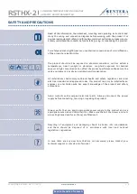
ATTENTION
The -F version of the product is not suited for 3-wire connection. It has separate
grounds for power supply and analogue output. Connecting both grounds together
might result in incorrect measurements. Minimum 4 wires are required to connect
-F type sensors.
The -G version is intended for 3-wire connection and features a ‘common ground’.
This means that the ground of the analogue output is internally connected with
the ground of the power supply. For this reason, -G and -F types cannot be used
together on the same network. Never connect the common ground of -G type
articles to other devices powered by a DC voltage. Doing so might cause permanent
damage to the connected devices.
MOUNTING INSTRUCTIONS IN STEPS
Before you start mounting the unit, read carefully
“Safety and Precautions”
.
Choose a smooth surface for installation (a wall, panel and etc.).
Follow these steps:
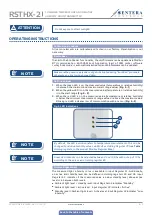
1.
Using a flat screwdriver, remove the front white cover by releasing the snap-fits
on its both sides (see
Fig. 1
Snap-fits release
).
2.
Insert the cables through the opening on the rear plate (See
Fig. 2
Mounting
dimensions
.)
3.
Using suitable fastening materials (not supplied), position the room sensor at
least 1,5 m from the floor. When planning the installation, allow enough clearance
for maintenance and service. Mount the sensor in a well-ventilated area. Mind
the correct mounting position and unit dimensions. See
Fig. 2
and
Fig. 3
.
Fig. 1 Snap-fits release
Fig. 2 Mounting dimensions
Pu
sh h
ere t
o
rele
as
e
2x Ø
6
59,8
9,
8
74,5
104,5
20
104,5
25,
6
70,
5
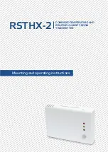
RSTHX-2
COMBINED TEMPERATURE AND RELATIVE
HUMIDITY ROOM TRANSMITTER

