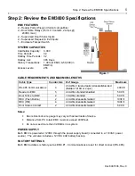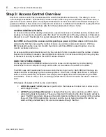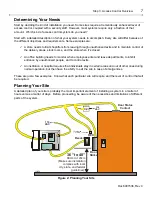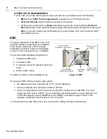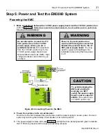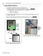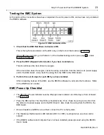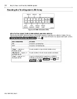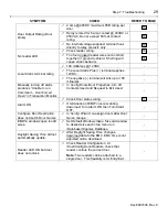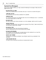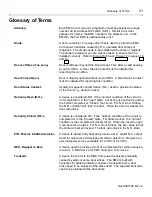
Step 4: Installation of the EM3000 System
19
Doc 6001536, Rev C
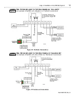
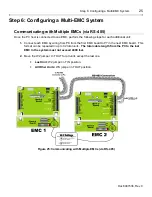
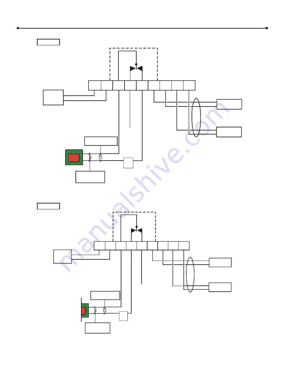
CONNECTING THE DOOR LOCK TO THE EMC BOARD AS “FAIL-SAFE”
is an example of the EMC with a Maglock in a “Fail-Safe” environment:
9
8
7
6
5
4
3
2
1
Open
Collector
Common Relay
Contact
Normally
Closed Relay
Contact
+12V, 100 mA max.
Fail Safe
Maglock
Maglock
N
o
rm
ally
Op
en
R
ela
y C
o
n
ta
ct
Not
Used
Diode (IN4004 or equiv.)
for counter EMF protection
MOV (Metal Oxide
Varistor) Siemens
S10K30 or equiv.
(-)
(+)
Door
Strike
P/S
Battery
Backed
CO
M
N.C.
N.O.
Dashed lines illustrate relay
on circuit board. Contacts rated
at 2 Amps continuous @ 28 VDC
power.
Supervised
Egress Sense
Supervised
Door Sense
2-twisted pair, 22 AWG,
stranded shielded cable
Belden 8728 or equiv.,
2,000 ft. Max.
1536F13
Sense 2
Ground
Sense 1
Ground
Figure 16: Fail-Safe Connections
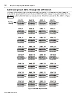
CONNECTING THE DOOR LOCK TO THE EMC PANEL AS “FAIL-SECURE”
Figure 17 is an example of the EMC with a Door Strike in a “Fail-Secure” environment:
9
8
7
6
5
4
3
2
1
Open
Collector
Common Relay
Contact
Normally
Closed Relay
Contact
+12V, 100 mA max.
N
or
m
ally
Ope
n R
ela
y C
ont
a
ct
Not
Used
Diode (IN4004 or equiv.)
for counter EMF protection
MOV (Metal Oxide
Varistor) Siemens
S10K30 or equiv.
(-)
(+)
Door
Strike
P/S
Battery
Backed
CO
M
N.C.
N.O.
Dashed lines illustrate relay
on circuit board. Contacts rated
at 2 Amps continuous @ 28 VDC
power.
Supervised
Egress Sense
Supervised
Door Sense
2-twisted pair, 22 AWG,
stranded shielded cable
Belden 8728 or equiv.,
2,000 ft. Max.
1536F14
Fail Secure
Strike
Sense 2
Ground
Sense 1
Ground
Figure 17:Fail-Secure Connections

