Step 5: Power and Test the EM3000 System
21
Doc 6001536, Rev C
Step 5: Power and Test the EM3000 System
Powering the EMC
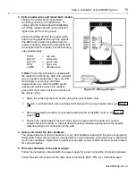
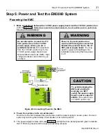
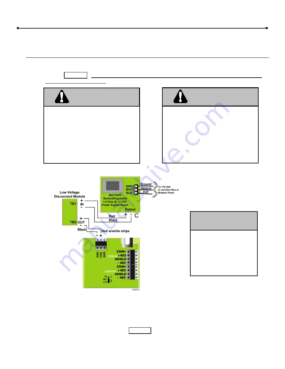
1. Make connections between the 12 VDC power supply board and the 110 VAC junction box
(refer to Figure 20): Remember to switch the local breaker to the off position prior to performing
this step of the installation!
Figure 20: Connecting Power to the EMC
2. Power the system via the circuit breaker:
Once the connection between the junction box and the power supply is secure, power the main
system by returning the building circuit breaker to its normal position.
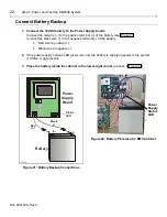
3.
The power supply’s status LED (see Figure 21) will light with an amber/greenish glow to indicate
that 110VAC is present and the supply is operating properly.
Do not attempt to connect the 110
VAC junction box to the 12 VDC
power supply unless you are a
qualified electrician.
All connections
from the 110VAC junction box to the
12 VDC power supply should meet
National Electrician Code (NEC). High
voltage accidents can be fatal to you
or others.
WARNING
Power to the local junction box
must be OFF during the connection
between the junction box to the 12
VDC power supply board.
You may
need to supply extra lighting to the
installation area during the time power
is off.
WARNING
To avoid damaging the
EMC and voiding its
warranty, do NOT
switch the power supply
board’s power output to
24VDC.
The system runs
on 12VDC power only.
CAUTION

