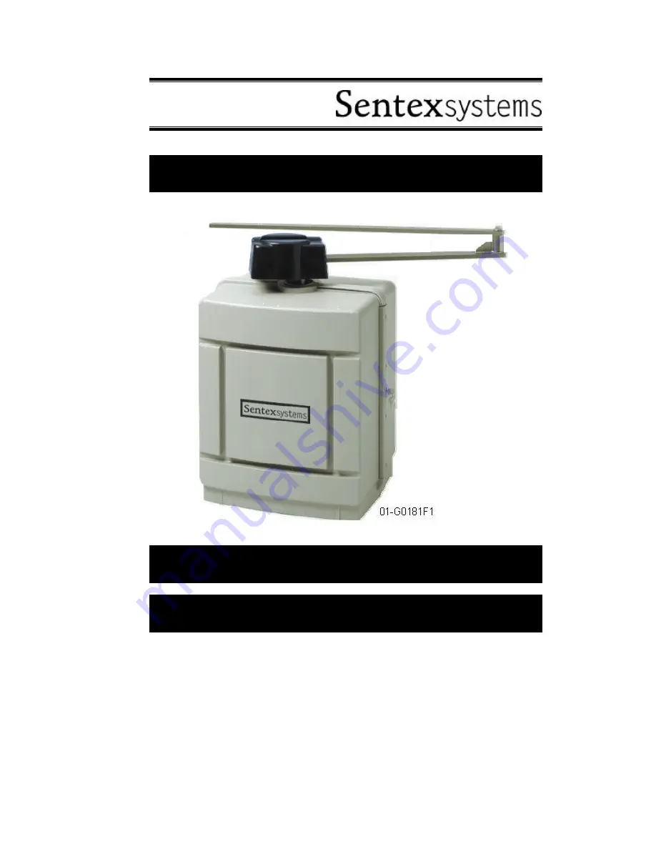
background image

Doc 01-G0181

Rev A

Installation Instructions

Swing Gate Operator

Model SW2200

Summary of Contents for SW2200

Page 1: ...Doc 01 G0181 Rev A Installation Instructions Swing Gate Operator Model SW2200 ...

Page 2: ...e Connections ______________________________ 14 Setup ______________________________________________________________ 14 Device Connections _____________________________________________________ 16 Operator Programming Menu LCD Screen ________________________ 17 Definitions and Options __________________________________________________ 17 Troubleshooting______________________________________________...

Page 3: ...ION is only permitted for property damage accidents PASSPOINT A reference point to set find open close limits When gate reaches passpoint PP LED blinks Important Safety Information WARNING Read and follow all instructions TO REDUCE THE RISK OF INJURY OR DEATH Never let children operate or play with gate controls Keep the remote control away from children Always keep people and objects away from th...

Page 4: ...N CONTACT SENSORS E G PHOTOCELL Read the following for gate operators utilizing non contact sensors See instructions on the placement of non contact sensors for each type of application Exercise care to reduce the likelihood of nuisance tripping To prevent gate entrapment install non contact sensors on both sides of the gate to cover the gate perimeter during closing and opening LOOP VEHICLE DETEC...

Page 5: ...garages retail store or other building servicing the general public Required additional equipment Type B1 non contact sensor or Type E an audio alarm CLASS III Industrial Limited Access Vehicular Gate Operator A vehicular gate operator or system intended for use in an industrial location or building such as a factory or loading dock area or other locations not intended to service the general publi...

Page 6: ...and follow your local construction codes when connecting power General guidelines are Line voltage required is 115 VAC 10 103 127 single phase Wire size accessory power 18 gauge recommended Line amperage Required 15 Amps Max Device controls any insulated wire can be used 18 24 gauge recommended Wire size operator power see Wire Sizes and Distances on page 24 NOTE The operator is permanently wired ...

Page 7: ...s are made to the lower half exposed half of the front panel PCB Provisions are made for J2 Safety edge open trailing edge contact sensor N O N C J8 Hold open no timer Single Button J3 Safety edge close leading edge contact sensor N O N C J9 Photo eye non contact sensor N O N C Contacts J4 3 loop detectors JP5 JP6 JP7 JP8 Output relays for lights etc J5 Close Open w Timer JP5 JP6 JP7 Master Slave ...

Page 8: ...CTIONS OPTION Sentex Systems recommends18 20 gauge wire for the minimal wattage required to run a pair in master slave setups WHITE BLACK CLOSE RELAY STOP RELAY OPEN RELAY MASTER RED GREEN SLAVE J 7 S T O P J 8 J 5 N C S T O P J 8 H O L D S IN G L E O P E N B U T T O N 01 20211F2 COM COM COM COM COM COM Figure 4 ...

Page 9: ...Specifications 9 Doc 01 G0181 Rev A FULL BATTERY BACKUP OPTION 24 hours continuous operation with normal use of accessory This is the only operator offered with transparent battery backup ...

Page 10: ...d is level and 2 to 4 above ground line 5 Sink 4 1 2 x 6 minimum length L bolts not supplied as detailed in Figure 6 and Figure 7 The bolts should protrude 1 above the pad The shipping crate bottom may be used as a bolt pattern template 6 Allow concrete to set for 2 days before installing operator 7 If there is existing concrete on the site use 1 2 anchor bolts not supplied to secure the unit If n...

Page 11: ...tions 1 Ensure all power is disconnected 2 Prepare the site see Site Preparation p 10 3 Pull and label wires for power and control 4 Bolt operator in place see Figure 8 Use washers to level operator 5 Attach Crank arm see Figure 9 01 G0181F8 Figure 8 01 G0181F9 Figure 9 6 Attach gate bracket at fence 31 from top of pad see Figure 10 and approximately 36 from gate hinge 5 31 Gate 01 G0181F10 Figure...

Page 12: ...p when the gate is closed see Figure 13 OPTIMUM CLOSED POSITION 01 G0181F13 Figure 13 9 Open gate with quick disconnect see Figure 9 and manually swing gate to the open position 10 When open the gate should travel at about 95 degrees and the crank arm should overlap parallel the extension arm see Figure 14 11 Lubricate gate pivot and elbow joint with medium weight lubricant superlube or equivalent...

Page 13: ... operator power switch is still off Check if operator does not run beep or function and LED s are off 4 Turn operator on Listen for 2 beeps The LCD should read LIMITS MENU NOTE If limits have been previously set the menu will read OPERATION NORMAL with the status displayed underneath it CAUTION If you do not know the limit settings reset limits according to the Basic Setup and Device Connection ch...

Page 14: ... disconnect see Figure 16 and check that the gate swings freely 4 Lock quick disconnect see Figure 16 5 Turn line power on The LCD screen should display the Limits Menu if limits have not been set CAUTION The unit should not move If it does shut off power and check all connections before proceeding NOTE The operator is shipped from the factory without limits If limits have been previously stored t...

Page 15: ...ot near center loosen 2 nuts with 1 2 wrench Using the buttons run gate to center position Re engage the passpoint and tighten nuts 12 Using the buttons continue running gate to open position crank arm and extension arm parallel and overlapped and press enter 13 LCD screen reads PRESS ENTER TO TEST Now press enter and the gate will self test by closing opening and closing LED s will flash until se...

Page 16: ...r to the electrical box according to the instructions on page 6 NC normally closed terminals are required That is you must either connect them for use or jumper them non use The operator will not run without the NC terminals wired to an NC device or otherwise shorted These terminals are identified by safety bars see Figure 20 J7 STOP J2 SE OPEN Safety Edge Open J3 SE CLOSED Safety Edge Closed J9 P...

Page 17: ...to run Closing Midstop Gate in any position other than closed or open and has not received any run commands Opening The operator has received a command to open and is opening the gate Open Gate is in the open condition and has not received any commands to run LIMITS MENU You may select the limits menu by scrolling thru the menu buttons This menu will be visible if the operator does not have limits...

Page 18: ...ngle Button connected at the J8 input connector programming feature allows you to configure the single button function i e how the gate reacts after you press the single button Selectable options include the following GATE CONDITIONS PROGRAMMABLE FUNCTIONS POSSIBLE STOP OPEN ONLY OPENING STOP NO TMR RST STOP CLOSING REVERSE MID STOP OPEN AT MID STOP MID STOP REVERSE Table 2 Programmable Options If...

Page 19: ...hes when hall sensor trips TQ Displays relative torque of the operator PASSPOINT FLAG P flashes upon seeing the passpoint D states that the entrapment is disabled ENTRAPMENT MODE T Normal torque measurement E Indicates overtorque entrapment has occurred P Indicates a position entrapment has occurred TQ LIMIT Self adjusting limit that triggers TQ entrapment This value is different for ramp up and r...

Page 20: ...apment level of 25 No Position or Speed Verify with the Troubleshooting Screen see page 19 WARNING Do not run system without hall sense speed sense for more than 1 minute as overheating will occur 1 Check sensor harness for connection and security see Figure 22 2 Adjust sensor by loosening bracket screws and inserting sensor until it barely touches the target disk inside the motor 3 If motor conti...

Reviews: