- 31 -
4.
Push the manual push rod to expose the male drive cable connector. Depress the sleeve of the female source
assembly connector and disengage the drive cable connector. Store the manual push rod tool on the actuator
by screwing it into the storage provision.
5.
Place the protective cap onto the locking mechanism, and rotate the selector ring from the “connect” position
to the “lock” position. Engage the plunger lock and remove the key.
6.
Perform a radiation survey on the Model 989 exposure device at the surface to ensure the measurable dose
rate is no greater than 2 mSv/hr (200 mR/hr). Secure the exposure device into the reusable transport and
storage case.
D.
System set-up using crank-out remote controls
1)
Perform a survey on the Model 989 exposure device to ensure the radiation level is less than 2 mSv/hr (200
mR/hr) on the surface. Perform a daily inspection of the exposure device and control assembly as described
in the daily inspection section.
2)
Unlock the plunger lock with the key. Remove the lockable protective cover by rotating the selector ring
from the “lock” position to the “connect” position. The protective cover will disengage from the exposure
device lock mechanism. The connector end of the source assembly will protrude approximately 0.4 inches (10
mm) out of the locking mechanism (See Figures 19 a through c).
3)
Remove the protective cover from the control assembly. Slide the remote control connector assembly's collar
back, and open the jaws to expose the male portion of the control cable connector (i.e. the ball-end on the
control cable connector). Press back the spring-loaded locking pin of the source assembly connector with a
thumbnail and engage the male and female portions of the connectors. Release the locking pin of the source
assembly connector, and check that the connection is secure.
4)
Close the jaws of the control cable connector over the joined connectors. Slide the remote control connector
assembly collar over the connector jaws.
5)
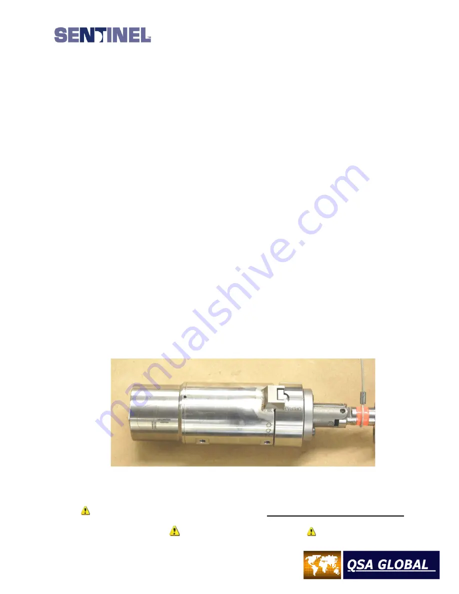
Push the connector assembly collar towards the locking mechanism while rotating the lock selector ring from
“connect” to “operate” position. This will mechanically link the two mechanisms together.
Figure 24 – 989 with Control Assembly Connected and Lockslide in Secured position
DO NOT push the lock-slide into the expose position. Leave the lock-slide in the secured position until
the radiographic set-up is complete and personnel have left the immediate area.
IMPORTANT WARNING
Summary of Contents for 989
Page 1: ...MAN 037 October 2017 ...


