- 32 -
The control cable connector is made from hardened steel and should never be left unprotected or forced into a
connection with the source assembly’s connector as this could damage the connector over time leading to
breakage during use.
ALWAYS manually move the sleeve of the source assembly connector to the OPEN position when connecting and
disconnecting the control cable connector from the source assembly connector.
ALWAYS use the protective cover whenever the remote controls are not connected to the exposure device.
E.
Operating instructions using crank-out remote controls
1)
Securely mount the Model 989 exposure device to the pipeline using the fixture kit or other secure
mechanisms.
2)
When performing SCAR technique, determine the thickness of shielding required to attenuate the primary
beam after it passes through the material being inspected. Shielding considerations must include the size of
the area the primary beam will produce at the back shielding. Secure the back shielding behind the
radiographic film cassette. Post the “restricted areas” according to national regulations and restrict access to
the area to radiographic personnel only.
3)
Lay out the remote control conduits as straight as possible, with no bend radii less than about 36 in
(approximately 1 m). Avoid any risk of crushing the remote control conduits by falling objects, moving
vehicles or closing doors, etc. The remote control crank mechanism (operator's hand-crank) should be
placed as far away from the source focal position as possible (preferably behind shielding). Remote controls
are available in standard lengths from 25 feet (7.6 meters) up to 50 feet (15.2 meters).
4)
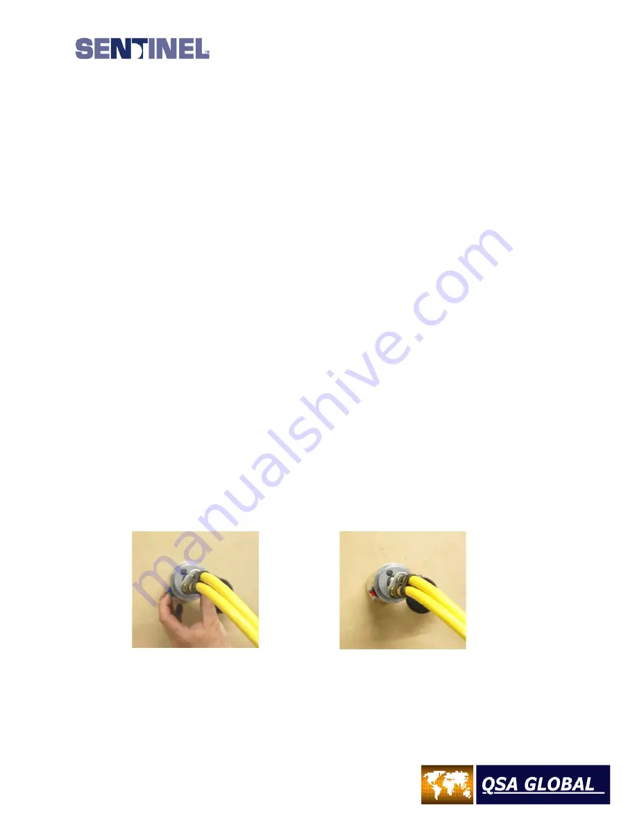
Perform a test exposure by pushing the lock-slide with the
GREEN MARKING
, laterally from left to right
(as viewed from behind the projector) until the lock slide snaps into the EXPOSE position. A
RED
MARKING
will appear where the lock-slide was previously positioned. The red marking indicates the source
assembly is unsecured when using standard remote controls.
Retreat to the area where the remote control crank is located. Verify the area is under restricted access.
Turn the hand crank approximately ¼ of a full revolution in the “expose” direction (counterclockwise) until
the source assembly stops. The source will travel a distance of approximately 3 inches (7.6 cm). Depending
on the device orientation, place the control crank brake in the “on” position to keep the source in the beam
port. Perform the required radiation surveys to verify the adequacy of the restricted area posting.
Figure 25 – 989 with Lockslide in
Secure/Locked Position and
Controls Attached
Figure 26 – 989 with Lockslide in the
Unlocked/Open Position and Controls
Attached
5)
To terminate the radiographic exposure, set the brake to OFF and rapidly turn the crank handle in the
RETRACT (clockwise) direction until it no longer moves, and the automatic locking mechanism triggers the
lockslide. When operating the device, you may hear the lock-slide ‘click’ back into its original position
depending on the ambient noise level at the job site. From the remote control crank you may be able to
observe the
GREEN MARKING
on the lock-slide bar which indicates the source assembly has been secured.
Summary of Contents for 989
Page 1: ...MAN 037 October 2017 ...


