


- 53 -
7)
Perform the following inspections of the control cable:
i.
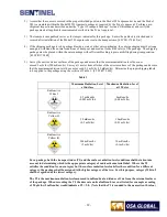
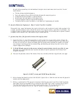
Use the Model 550 NO GO gauge to inspect the control cable connector for wear. Closely inspect the
connector for bends or cracks in the neck (shank) area and dented areas on the ball of the connector. Remove
the control cable from service if any cracks or bends in the shank or dents in the ball of the male connector are
found during this inspection. The male connector should not be bent at an angle greater than 15 degrees from
the axis of the control cable in the area where it is crimped. Using your hands, attempt to twist or rotate the
male connector off the control cable. If any movement is possible during this test, the control cable must be
removed from service and the male connector must be replaced.
ii. Carefully inspect the control cable directly behind the remote control cable connector and approximately 12 in
(305 mm) beyond the male connector looking for the following anomalies:
•
Cuts, breaks, nicks or fraying in the spiral windings of the cable.
•
Kinks or permanent bends.
•
Rust (red oxide) on the inner and outer core of the cable.
•
Uniformity of the spacing between the outer helical windings of the cable. Check for flattened areas and
excessive wear that reduces the cable's outer diameter less than 0.183 in (4.7 mm).
•
Perform a flexibility (spring) test of the cable by bending the connector end of the cable into a ‘U’ shape
and then releasing it. A cable that is bent/released and does not spring back into an essentially straight
shape is indicative of internal corrosion of the cable. The cable must be removed from service.
•
Carefully examine the cable in the area of the control crank assembly looking for cuts, breaks, fraying, rust,
unusual stiffness and uniformity of the spacing between the outer spiral windings.
•
Examine the entire length of cable looking for defects described above.
If a control cable is deemed as defective during this inspection, remove it from service and tag it with a label to
prevent inadvertent use.
The control cable (Model 550 male) connector must be replaced at intervals
not to exceed five (5) years
.
Maintenance program administrators must maintain traceability records for replacement of all ‘Safety Class A’
designated components.
8)
Lightly lubricate the control cable using MIL-G-23827B (or C), MIL-PRF-23827C, or equivalent grease. Apply
additional grease to the first 3 ft. (approximately 1m) of control cable (male connector end).
9)
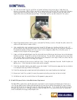
Clean the exterior of the remote control conduits using clean rags and a detergent. Remove all dirt and grease from
the polyvinyl conduits and swaged fittings. Carefully inspect the entire length of remote control conduits for cuts
and melted areas. Repairs to cut or melted areas can be accomplished by taping the area with 3M™ yellow
polyvinyl tape (or black polyvinyl electrical tape). The tape will prevent the ingress of water and other liquid that
would cause corrosion of the remote control conduit's inner braids and the remote control cable. Look and feel for
dents and depressions in the remote control conduits. Minor dents can be rounded out by gently tapping the area
with a small hammer.
Examine the control conduits where they protrude from the swage fittings, looking for bulges or cracks in the
polyvinyl. Remote control conduits with large dented areas or cracks/ bulges near the swage fittings should be sent
to the manufacturer for repairs.
Clean the interior of both remote control conduits by pouring 4-5 oz (100 ml) of clean solvent into one end. Use
compressed air to blow the solvent through the entire length of conduits into a clean white cloth attached to the
opposite end. Repeat this cleaning process until the solvent blown through the conduit comes out clean. Use the
compressed air to thoroughly dry the interior of the conduit. Residual solvent left in the remote control conduit will
dilute the lubrication applied to the remote control cable diminishing the protective qualities.
Check the swage fittings to ensure the threads are not stripped and are clean. Using your hands, attempt to twist or
rotate the swage fittings off the control conduits. If any movement is possible, the control conduit must be removed
from service and new swage fittings must be installed.
Summary of Contents for 989
Page 1: ...MAN 037 October 2017 ...


