

- 58 -
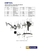
Remove the spring duplex strain relief assembly and examine the control conduits where they protrude from the
swage fittings, looking for bulges or cracks in the polyvinyl. Remote control conduits with large dented areas or
cracks/ bulges near the swage fittings must be sent to the manufacturer or authorized service center for repairs.
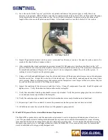
Clean the interior of both remote control conduits by pouring 4-5 oz (approx.100 ml) of clean solvent into one end.
Use compressed air to blow the solvent through the entire length of conduits into a clean white cloth attached to the
opposite end. Repeat this cleaning process until the solvent blown through the conduit comes out clean. Use the
compressed air to thoroughly dry the interior of the conduit. Residual solvent left in the remote control conduit will
dilute the lubrication applied to the remote control cable diminishing the protective qualities.
Check the swage fittings to ensure the threads and hex nuts are not stripped and are clean. Using your hands,
attempt to twist or rotate the swage fittings off the control conduits. If any movement is possible, the control
conduit must be removed from service, and new swage fittings must be installed.
10)
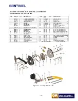
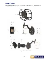
Remove the crank arm assembly with brake from the control crank assembly by removing the 5/16 inch hex bolt and
washer. Check the hand crank knob (tee-handle) pin (part number 95010) for looseness or excessive wear. Replace
a worn knob pin by removing roll-pin (part number PIN024), replace knob pin (part number 95010), and then insert
a new roll pin (part number PIN024). Check brake assembly for proper on and off operation, and verify the spring
tension is adequate to maintain the set position. Compare the crank arm assembly to a new crank arm assembly for
conformity to shape. If required, a bent crank arm can be mounted into a vise, and bent back into its original shape.
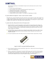
Disassemble the control crank assembly by unscrewing the six socket-head screws (part number SCR252) using a
1/8 inch Allen wrench.
Separate the drive gear cover (steel plate, part number 95002-6) from the molded grip handle body of the control
crank. Inspect the drive gear cover plate label (part number 95007-01 or 95006-01) to ensure the “expose” and
“retract” and arrows indicating the direction of travel is legible. Replace the operator instruction label if damaged or
illegible.
Inspect the molded grip handle body (part number 95003-6) to ensure the tubular spacers (part number 95003-6) are
all present. The tubular spacers prevent over-compression and distortion of the black molded grip handle when the
six socket-head screws are tightened. Inspect the black plastic handle body for cracks near the conduit fittings and
the ball bearing housing. Inspect the black plastic handle body for its general condition to ensure it’s not deformed
as the result from exposure to high temperature, and there are no cracks or perforations in the plastic housing that
could allow the ingress of foreign materials such as water, sand, mud or fly ash.
Disassemble, clean and degrease the drive gear (part number 95005), interior surface of the molded grip handle and
drive gear cover (part number 95002-6), the two conduit fittings and the external surfaces of the ball bearings (part
number BBS032). Inspect the ball bearings to ensure the rubber seals are not cracked or worn through. Check the
ball bearings for smooth and free movement by holding the inner hub stationary and rotating the outer hub. These
are sealed ball bearings and do not require additional lubrication.
Inspect the two rubber seals, 15 mm seal (part number RIN024) and the large O-ring seal (part number RIN026) for
cracks, cuts or abrasions that would warrant replacement. If the rubber seals are deemed satisfactory after this
inspection, apply a light coating of grease to these seals.
Clean the drive gear in solvent using a brush to dislodge any dirt between drive gear’s teeth. Inspect the drive
wheel's gear teeth looking for broken or bent teeth. If the drive wheel has broken or bent teeth, use a file to grind the
tooth flush with the drive wheel. Up to three consecutive teeth can be missing from the drive wheel before a
replacement is required.
Light rust may be removed from the wear strip using fine sandpaper and machine oil.
Lightly grease the wear strip before reassembling.
11)
Reassembly of the remote control handle assembly:
Summary of Contents for 989
Page 1: ...MAN 037 October 2017 ...


