


- 59 -
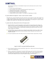
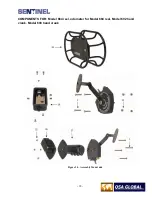
Install the ball bearing (part number BBS032) into the steel insert of the molded grip handle. Insert the drive gear in
the ball bearing already placed in the crank housing. Rotate the drive gear (part number 95005) to ensure free
movement and proper seating. Install the second ball bearing (BBS032) onto drive gear shaft and rotate to ensure
proper seating of the installed components. Install the lubricated large diameter O-ring seal onto the back side of the
drive gear cover plate and seat into the molded grip handle body. The serial number of the drive gear cover plate
should be positioned five o’clock position relative to the hand grip at the six o’clock position. Install the lubricated
15 mm rubber seal onto the drive gear shaft while making sure it’s seated within the drive gear cover plate.
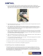
Apply Loctite 242 onto the first four threads of socket head screws (part number SCR252). Ensure the tubular
spacers (part number 95003-6) are all present. The tubular spacers prevent over-compression and distortion of the
black molded grip handle when the six socket-head screws are tightened. Install and hand tighten the six socket
head screws (part number SCR252) and flat washers (part number WSH047) into the back of the molded grip handle
body using the 1/8 inch Allen wrench. Install the crank arm assembly onto the drive gear shaft at the 9:00 o’clock
position relative to the 6:00 o’clock position of the hand grip. Apply temporary Loctite 242 to the first four threads
of the 5/16 inch bolt. Install the 5/16 inch hex-head bolt (part number SCR219-03) and washer (WSH045) and hand
tighten using a ½ inch open-end wrench.
After assembly, verify the control crank mechanism is properly assembled by turning the crank arm. It should spin
freely. Check the operation of the brake’s plunger knob.
For reel type controls, apply Loctite 242 to the first four threads of the flat socket head screws. Mount the control
crank housing on the reel type frame with the two flat socket head screws (part number SCR350) and 2 thrust plates
(part number 95063).
After assembly, perform a check to ensure the control crank will turn freely. Set the brake plunger knob to the ON
position (engaged on the drive gear cover plate) and attempt to turn the handle using moderate pressure. Do not
apply excessive force. Run a section of the control cable through the control crank to ensure the control crank
operates easily without snags or resistance.
12)
Clean the 661 safety connector assembly using a brush and solvent. Ensure the movable jaws of the safety
connector are not excessively loose or worn where they swivel on the Spirol pins (part number PIN016). Attempt to
push the pins out using the back end of a 1/8 inch drill bit or a drift punch. If they can be moved by pushing, replace
the pins. Visually look for cracked Spirol pins from both sides of the safety connector. Replace the Spirol pins if
there is any evidence of cracked or broken pins. Examine the connector collar for bent or loose connecting pins and
excessive wear on the inner-mating surface. Examine the face of the connector body where the control cable
protrudes, and verify that long-term usage has not chamfered the area.
13)
Re-assembly of the Remote Control Unit:
If required, install the spring duplex strain relief assembly on the opposite end of the remote control conduits from
which it was removed. This will promote even wear of the remote control conduits. Reposition the spring strain
relief assembly by sliding it down the entire length of conduits to the opposite end. Apply heavy-duty shrink wrap
or wrap PVC tape near the end the spring to prevent chafing of the conduits. Reattach the remote control conduits to
the safety connector assembly. Attach the EXPOSE sheath (yellow side of the joined conduits) to the EXPOSE side
of the control crank assembly.
CAUTION! Do not over-tighten these fittings.
Lay the remote control conduits out in a straight line or a wide loop. Feed the end of the control drive cable into the
conduit as far as it will go. As the control cable is being fed into the remote control conduits, feel for any resistance
that indicates damage of the remote control conduit.
Turn the control crank handle in the RETRACT direction until the end of the control cable is protruding. Screw the
safety stop spring onto the end of the control cable approximately 2 in (50 mm) from the end.
Summary of Contents for 989
Page 1: ...MAN 037 October 2017 ...


