- 17 -
SECTION III – OPERATIONAL PRINCIPLES
A.
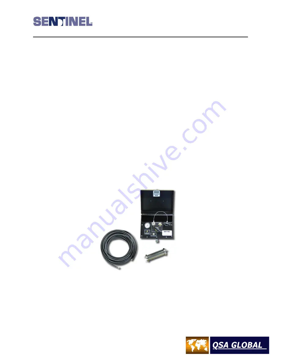
Principles of Operation - Pneumatic actuator and air pump control
The source assembly, which contains the radioactive sealed source capsule, is positioned such that the sealed source
capsule is located in the shielded storage position in the exposure device. This sealed source assembly is attached to the
pneumatic actuator (part number ELE-027). A 15 to 50 foot (4.5 to 15 meters) air hose with quick connect fittings is
attached between the device pneumatic actuator and the air pump control. Before the radiographic exposure, the lock
slide on the exposure device is pushed into the expose position. Evacuate all personnel from the immediate area. After
pressurizing the air pump control to approximately 30 p.s.i., the control switch is rotated from the “off” to the “expose”
position, the actuator will push the source from its shielded storage position to exposed position inside of the beam port
of the Model 989 exposure device. The air pump control must be re-pressurized after turning the switch to the “exposed”
position to maintain a pressure of 25 p.s.i. during the radiographic exposure. The emergent beam will depend on actual
collimation of the exposure device beam port. During the performance of radiography, the radioactive sealed source
assembly never leaves the exposure device.
To terminate the radiographic exposure, the air pump control switch is turned to the “off” position which exhausts the
pressurized air from the air hose and pneumatic actuator. Depressing the “Zero Pressure” valve on the control completely
exhausts the pneumatic system. The steel return spring contained within the pneumatic actuator forces the source rod to
the fully shielded position. The lock slide on the lock mechanism is intended to remain in the expose (red) position until
all radiographic operations are completed. Before the pneumatic actuator is removed from the Model 989 exposure
device, a manual push rod (part number TOL012) is screwed into the top of the actuator source rod and pulled until the
lock slide actuates and secures the source assembly (green position) for transport. The pneumatic actuator can then be
safely removed and the lockable protective cap installed for transport or storage.
Figure 11 - Model ELE072 Actuator Assembly with Model 86550 Pump Box and air hose
Summary of Contents for 989
Page 1: ...MAN 037 October 2017 ...


