- 28 -
SECTION V- OPERATING INSTRUCTIONS
A.
System Assembly Using the Pneumatic Actuator
1)
Perform a daily inspection of the exposure device, pneumatic actuator and air pump control as described in
the daily inspection section.
2)
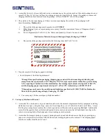
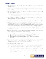
Unlock the plunger lock with the key. Remove the lockable protective cover by rotating the selector ring
from the “lock” position to the “connect” position. The protective cover will disengage from the exposure
device lock mechanism. The connector end of the source assembly will protrude approximately 0.4 inches
(10mm) out of the locking mechanism.
Figures 20 a through c – Model 989 with Plunger Lock engaged, Unlocking Plunger Lock and with
Protective cover removed
3)
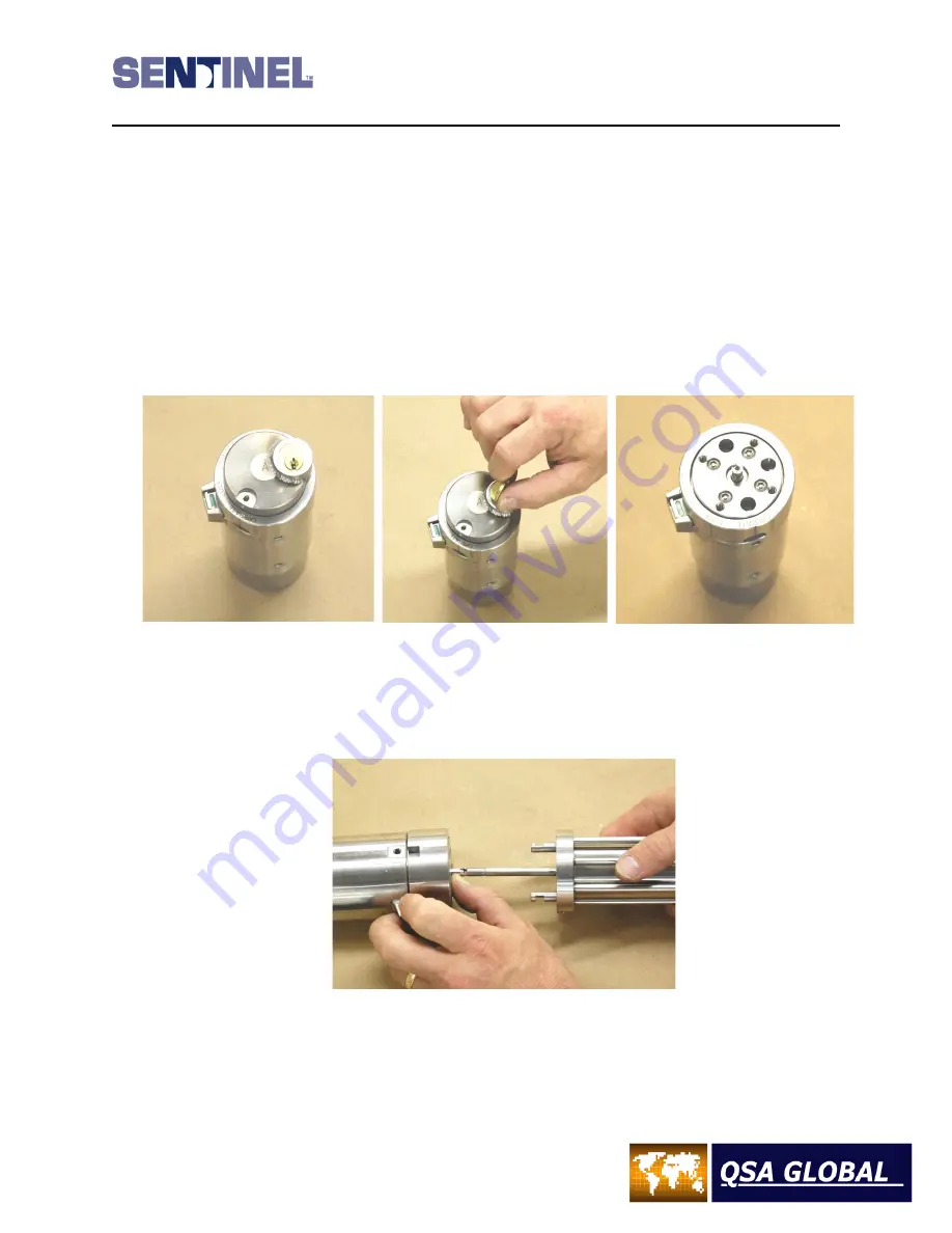
Connect the male connector of the actuator assembly rod to the source connector. Draw the exposure device
and the pneumatic actuator together, aligning the two prongs on the actuator to the holes in the exposure
device lock mechanism.
Figure 21 – Connection of ELE027 Actuator to Source Connector in Model 989
Summary of Contents for 989
Page 1: ...MAN 037 October 2017 ...


