background image


- 49 - 

A.


Quarterly Maintenance Checks of the 989 device  


1)


Survey the external surfaces of the device to assure that the radiation levels do not exceed 2 mSv/hr (200 mR/hr). 
 

2)


Clean and inspect the exterior of the device for obvious damage.  Report any defect that may impair its safe 
operation and withdraw it from service until repairs can be made.  If a defect is found during the inspection, use a 
status indicator, such as a tag or label, to prevent inadvertent use.     
 

3)


Check that the radiation trefoil, the “Danger Radioactive Material” and the “Rayonnement Danger Radiation” 
warning information engraved on the outer shell is legible.  Do not cover the warning with any other labels.  Verify 
the source identification is present and legible.    
 

4)


Check the plunger lock on the storage cover to ensure it locks the exposure device when the key is removed.  The 
lock must function to prevent access or operation by unauthorized personnel. 
 

5)


Inspect the lock mechanism for loose or missing fastening hardware.  Also, grasp the lock mechanism and attempt to 
move it side -to-side and up-and-down to determine if the lock mechanism is loose.   
 

6)


Use the Model 550 NO GO gauge on the source assembly connector to verify the female connector is not worn or 
damaged.  Actuate the movable sleeve on the source assembly connector to verify it moves freely and does not stick 
in the connect position.  
 

7)


A misconnect test on the exposure device including the radioactive source assembly and remote controls effectively 
tests the integrity of the entire locking system.  This test detects long term wear (or damage) of the interrelated 
failsafe system including identification of any excess wear on the safety connector assembly, the control male 
connector, the exposure device automatic securing mechanism and the source assembly connectors simultaneously. 
 

NOTE:  Component wear occurs to both the control assemblies and the device locking mechanisms over time, 
therefore, to ensure acceptable equipment operation, the misconnect test must be performed on each device 
lock assembly and control assembly that will be used for radiographic operations.  All remote 
controls/pneumatic actuators must be tested with any exposure device it may be used with for radiographic 
operations to ensure no possible combination could fail the misconnect test. 


WARNING: 

The test should only be performed by personnel that are formally trained, authorized 
and thoroughly familiar with annual maintenance procedures.  This test is performed 
by engaging the remote control connecting plug assembly into the exposure device’s 
locking mechanism 

WITHOUT

 first engaging the control cable connector within the 

source assembly connector.


Perform a misconnect test of the crank-out remote control/pneumatic actuator safety plug assembly and drive cable 
connector and lock mechanism and source assembly connector.  

Do not

 connect the drive cable connector to the 

source assembly connector.  Attempt to engage the crank-out remote control/pneumatic actuator safety plug 
assembly to the device lock mechanism, and rotate from the “connect” position to the “lock” position.  


WARNING:


Do not

 rotate the selector ring beyond “lock” during this test.  If rotated beyond 

the “lock” position, there is a risk of losing control of the radioactive source assembly. 


If the misconnect can be made, remove the equipment from service until repairs have corrected the problem.  
Contact QSA Global, Inc., or an authorized QSA Global, Inc. approved service center if you have questions 
regarding the misconnect test. 

NOTE:

  When the Model 989 exposure device is returned to the manufacturer for source reloading it can receive 

formal servicing.  The servicing should be done at least annually if used under normal operating conditions. 


8)


Routine Quarterly Maintenance Records 
 

Summary of Contents for 989

Page 1: ...MAN 037 October 2017 ...

Page 2: ...the Model 989 Exposure Device 21 C Daily Inspection of the crank out remote controls 22 D Daily Inspection of the pneumatic actuator and the air pump control 24 E Fixture Kit Component Inspection 26 SECTION V OPERATING INSTRUCTIONS 28 A System Assembly Using the Pneumatic Actuator 28 B Operating instructions for the Pneumatic Actuated system 29 C Disassembly of the Pneumatic Actuated system after ...

Page 3: ...ol 50 D Model 989 Exposure Device Annual Maintenance Requirements 51 E Annual Maintenance for Standard Remote Controls e g Models 692 693 664 52 F Annual Maintenance Extreme Condition Remote Controls 56 G Annual Maintenance Records 60 H Model 989 Series Safety Class A Components 60 1 Safety Class A Designation Items 60 2 Considerations of Safety Class A Items 60 SECTION IX LEAK TESTING 66 SECTION ...

Page 4: ...ROD INSERTED TO EXPOSE MALE CONNECTOR 25 FIGURE 17 ELE027 ACTUATOR WITH ROD EXPOSED 26 FIGURE 18 MODEL 86550 PUMP BOX CONNECTED TO ELE027 ACTUATOR ASSEMBLY 26 FIGURE 19 MAIN FIXTURE KIT COMPONENTS 27 FIGURES 20 A THROUGH C MODEL 989 WITH PLUNGER LOCK ENGAGED UNLOCKING PLUNGER LOCK AND WITH PROTECTIVE COVER REMOVED 28 FIGURE 21 CONNECTION OF ELE027 ACTUATOR TO SOURCE CONNECTOR IN MODEL 989 28 FIGUR...

Page 5: ...nts which include injuries are directly attributed to a failure of the radiographer to perform or supervise an adequate confirmatory survey It is imperative that the users of this transport container perform adequate radiation surveys of the transport container and exposure devices Surveys must be performed using a calibrated survey instrument before during and after source exchanges and before tr...

Page 6: ...se ONLY with a QSA Global manufactured approved actuator system or remote controls which meet operational and safety requirement as outlined in this manual and as approved under a specific license In order to use this equipment users within the USA and Canada must be specifically licensed to do so Applications for a license must be filed with the Materials Licensing Section of the appropriate U S ...

Page 7: ... radiographers to consider the primary beam area created at the film plane to determine shielding requirements for the technique The primary beam is shielded after passing through the specimen and film cassette to effectively reduce the working distances to the controlled areas Proper SCAR technique allows radiography to be conducted in areas congested with personnel and significantly reduces the ...

Page 8: ...tic lines and actuator are exhausted The return spring forces the sealed source assembly back into the fully shielded position regardless of the exposure device orientation Conversely if the air supply is interrupted during a radiographic exposure the sealed source assembly is automatically forced back into a shielded position B System Safety The Model 989 exposure device contained within an appro...

Page 9: ...Becquerels Curies are provided The Model 989 exposure device label provides the maximum capacity for Se 75 in Curies and Becquerels Partial compliance with the requirements in ISO 3999 2004 E is allowed for this device since it is classified as Category X C Model 989 System Components 1 Model 989 Radiographic Exposure Device The Exposure device with it s key lockable protective cover see Figure 2 ...

Page 10: ...ns In Canada collimation is limited to lead collimation with emergent beams of 30 X 60 degrees or 40 X 40 degrees The lead or tungsten collimation must be installed by SentinelTM QSA Global Inc or one of its authorized distributor service centers A cross sectional view of a Model 989 with a 40 X 40 degree collimated beam port is shown as a reference in Figure 3 2 Model 989 Exposure device pneumati...

Page 11: ...re device and may only be reloaded by QSA Global Inc or one of the authorized service centers Use of an unapproved source assembly may cause elevated dose rates on the exposure device The Model 97941 Model 98940 and Model 98941 source assemblies are designed to be re usable After the source assembly is re loaded with a new sealed source within a shielded enclosure the source assemblies are joined ...

Page 12: ...sembly and the contained sealed source capsule in the Model 989 may only be changed by QSA Global Inc or one of its authorized service centers Source changing and replacement or change in the collimation for this device requires the use of a shielded cell and specially designed tools Therefore all devices must be returned to QSA Global Inc or one of its authorized service centers for source replac...

Page 13: ...device when used with the supplied fixture kit can be configured and arranged in various orientations for achieve optimal exposures See Figures 9 and 10 for example configurations Appropriate shielding on and around the device is recommended to reduce undesirable scatter radiation Figure 9 Fixture kit used to secure the Model 989 exposure device parallel to a pipe Figure 10 Fixture kit used to sec...

Page 14: ...noramic beam industrial gamma radiography Model number Model 989 radiographic exposure device Length 7 5 inches 19 5cms without storage cover and shipping container Diameter 2 54 inches 6 5cm without storage cover and shipping container Mass 16 0 pounds 7 3 kg maximum Shielding 5 7 pounds 2 6 kg of tungsten plus 3 8 to 5 4 pounds 1 7 to 2 5 kg of lead or tungsten for the collimator Construction Tu...

Page 15: ...reloading Operating temperature range 40 F to 300 F 40 C to 149 C SentinelTM Model 989 actuators for radiographic exposures The Model 989 exposure device is compatible for use with SentinelTM manufactured crank out remote controls or air pressure actuators Part number ELE 027 For designed radiological safety the only crank out remote controls and air pressure actuators that can be used with the ex...

Page 16: ...be required in some countries Restricted Area Radiography must be performed only in a restricted area that is marked with the appropriate radiation warning signs and secured against unauthorized entrance Distance Since the source emits high levels of radiation it is good practice to operate the system from as great a distance as possible Shielding Whenever possible situate the radiographic exposur...

Page 17: ...ition to maintain a pressure of 25 p s i during the radiographic exposure The emergent beam will depend on actual collimation of the exposure device beam port During the performance of radiography the radioactive sealed source assembly never leaves the exposure device To terminate the radiographic exposure the air pump control switch is turned to the off position which exhausts the pressurized air...

Page 18: ...ring radiographic operations First the locking mechanism requires a deliberate action to enable exposure of the source assembly This is accomplished by coupling the control cable connector to the source assembly connector coupling the remote control connector to the exposure device locking mechanism and then pushing a lock slide from the SECURED GREEN MARKING position into the EXPOSE RED MARKING p...

Page 19: ...ve part s from use and label as defective When attaching the Model 989 to a pipe ensure the device is secure prior to exposure Damaged components and or an unstable attachment can allow the device to fall during an exposure This may cause damage to the device and controls and possibly prevent retraction of the source depending on the damage received and the distance dropped D Confirmatory Survey A...

Page 20: ...rom behind a radiation shield such as a heavy steel or concrete object or around the corner from a shielding wall Radiography must only be performed in areas which are properly controlled and clearly posted as specified by the applicable regulatory requirements While assembling the system it is important to keep the exposure device locked at all times except when operating Locked is defined as the...

Page 21: ...el 989 Exposure Device 1 Remove the Model 989 exposure device from the transport case and survey the surface of the exposure device to ensure the radiation level is less than 2 mSv hr 200 mR hr even when containing a source assembly with the maximum allowable activity This survey provides an operability check of the survey instrument that it is responding to radiation in addition to providing the ...

Page 22: ...grapher will only need to turn the hand crank approximately of a full revolution to expose the source into the beam port of device collimator During the first radiographic exposure the radiographer should take notice of the hand crank position relative to the handle when the source is manipulated to the exposed and the secured positions Two remote control conduits sheaths housings are attached to ...

Page 23: ...felt while rotating the crank handle with the brake in the ON position Inspect the control conduit fittings to verify they are secured to the control crank 4 Drive Cable Inspections i Inspect the control cable connector as it protrudes out of the connecting plug assembly The control cable connector should not be bent or at an angle exceeding 15 degrees relative to the control cable centerline If a...

Page 24: ...able connector must NOT GO into the hole of the gauge 2 The shank or stem of the control cable connector must NOT GO into the smaller of the two notches located on the side of the gauge 3 The width of the gauge must NOT GO into the female slot of the source assembly connector 4 After a positive connection between the control cable and source assembly connectors has been accomplished verify that th...

Page 25: ...han 7 lbs can cause the source to move into a non fully shielded position Do not use the pneumatic actuator if the threads of the actuator rod and push rod are stripped and do not engage Figure 15 ELE027 Actuator with Manual Push Rod Attached Figure 16 ELE027 with Push Rod Inserted to Expose Male Connector Visually inspect the male connector for cracks and wear on the main connector body shank and...

Page 26: ...n the control knob to the off position This will cause the actuator rod to retract into the actuator body Depress the zero pressure valve to completely exhaust the air from the system A reading of zero will register on the pressure gage E Fixture Kit Component Inspection Inspect the components of the fixture kit to ensure there is no damage to the components which could prevent safe attachment to ...

Page 27: ...evice the remote controls and fixture kit components prior to use Defective equipment that is discovered during the daily inspection must be removed from service until repaired or replaced All equipment removed from service must be identified with a status indicator tag label or tape to prevent inadvertent use by other radiography personnel ...

Page 28: ...er will disengage from the exposure device lock mechanism The connector end of the source assembly will protrude approximately 0 4 inches 10mm out of the locking mechanism Figures 20 a through c Model 989 with Plunger Lock engaged Unlocking Plunger Lock and with Protective cover removed 3 Connect the male connector of the actuator assembly rod to the source connector Draw the exposure device and t...

Page 29: ...made Place the air pump control behind shielding if possible or to the maximum length of the air hose if no shielding is available Air hose is available in lengths from 15 feet 4 6 meters to 50 feet 15 2 meters 4 Perform a test exposure by pushing the lock slide from the secured GREEN MARKING position to the expose RED MARKING position Retreat to the area where the air pump control is located Atta...

Page 30: ...tions They must maintain direct surveillance of the High Radiation area and control access to the Restricted Area which will be placed at much shorter distances than conventional crank out exposure devices C Disassembly of the Pneumatic Actuated system after use 1 Survey the external surfaces of the device to assure that the radiation levels do not exceed 2 mSv hr 200 mR hr 2 Remove the air hose f...

Page 31: ...ive cover will disengage from the exposure device lock mechanism The connector end of the source assembly will protrude approximately 0 4 inches 10 mm out of the locking mechanism See Figures 19 a through c 3 Remove the protective cover from the control assembly Slide the remote control connector assembly s collar back and open the jaws to expose the male portion of the control cable connector i e...

Page 32: ...l position as possible preferably behind shielding Remote controls are available in standard lengths from 25 feet 7 6 meters up to 50 feet 15 2 meters 4 Perform a test exposure by pushing the lock slide with the GREEN MARKING laterally from left to right as viewed from behind the projector until the lock slide snaps into the EXPOSE position A RED MARKING will appear where the lock slide was previo...

Page 33: ...the safety plug collar assembly from the lock mechanism 3 Depress the sleeve of the female source assembly connector and disengage the drive cable connector 4 Place the protective cap onto the locking mechanism and rotate the selector ring from the connect position to the lock position Engage the plunger lock and remove the key Figure 27 989 with Protective Cover Removed Figure 28 989 with Protect...

Page 34: ...cess to the device or restricted area iii Notify QSA Global Inc and the Responsible Regulatory Authority Advise of the situation giving as much detail as possible and obtain advice on further actions to take to return conditions to normal Information should include identification of the equipment involved the cause of the incident actions taken to establish a safe condition doses to all personnel ...

Page 35: ...t Packaging and Transport of Nuclear Substances Regulations Nuclear Substances and Radiation Devices Regulations Transport Canada Transport of Dangerous Goods Regulations Transport in the Great Britain is governed by the Radioactive Material Road Transport Great Britain Regulations A Type A Transport Package The locked Model 989 exposure device in either the approved 1400 Pelican Case storage and ...

Page 36: ...gravings of the warning Inspect the reusable storage transport case to verify all interior inserts used for blocking and bracing of the device are present and intact Inspect the exterior of the case for cracks perforations broken hinges and securing latches Ensure the Type A label is securely attached and the information is clearly legible Contact QSA Global Inc or one of its authorized service ce...

Page 37: ... 1906 d 10 CFR 71 47 Note If any of these limits are exceeded the Radiation Safety Officer must immediately notify the USNRC or applicable governing agency and the final delivering carrier 4 Inspect the package for any evidence of physical damage Record the results of this inspection on the Receiving Report Record on the Receiving Report the date source model number source serial number radionucli...

Page 38: ...d procedures for accident avoidance i e proper procedures for handling hazardous material packages OSHA or EPA training MSDS information Security Awareness Training In depth security training must be provided for facilities that are required to have a transport security plan Hazmat employees must be trained in the plan and its implementation An appropriate test must be administered and the followi...

Page 39: ...urvey at 1 meter from all sides of the exterior surfaces of the package and assure that the maximum radiation level does not exceed 0 1 mSv hr 10 mRem hr Determine the proper shipping labels to be applied to the package using the criteria of Table 1 49 CFR172 403 Table 1 Maximum Radiation Level at Surface Maximum Radiation Level at 1 Meter Radioactive White I 0 5 mRem hr 0 005 mSv hr 0 mRem hr 0 0...

Page 40: ...final package gross weight exceeds 110 lbs 50 kg mark the outside of the package with the gross weight 49 CFR 172 310 a 13 Properly complete the shipping papers indicating 49 CFR 172 203 i United Nations identification number Proper shipping name and Class Number 7 e g UN3332 Radioactive Material Type A Package Special Form Class 7 ii The letters RQ must appear before or after the proper shipping ...

Page 41: ...shipper s certification may be used I hereby certify that the contents of this consignment are fully and accurately described above by proper shipping name and are classified packaged marked and labeled placarded and are in all respects in proper condition for transport according to applicable international and national governmental regulations I declare that all of the applicable transport requir...

Page 42: ...178 except requirements within those parts relating to the reporting of incidents and decontamination the training requirements of subpart H of Part 172 and the shipping paper requirement of subpart C of Part 172 Authorized per 49CFR 173 428 This package conforms to the conditions and limitations specified in 49 CFR 173 428 for Radioactive Material Excepted Packages Empty Packaging UN 2908 ii Your...

Page 43: ...cense numbers and circumstances of the accident Call the Radiation Safety Officer promptly and give him as much information as possible 10 If a source should escape from the packaging the vehicle operator should make no attempt to restore the source by himself He should wait for assistance from the Radiation Safety Officer 11 If the vehicle is going to be used for storage of radioactive material a...

Page 44: ...nd if the truck was involved in an accident and cannot be driven away Know what immediate response is required by a T R employee if the vehicle is stolen or the radioactive material package is lost or stolen Have the ability to communicate immediately with the Trustworthy and Reliable Official TRO should they need assistance or have a security related question Know to report immediately to the TRO...

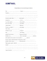
Page 45: ...reading ________________________________ Final reading ________________________________ Radiation area signs ____________________ Packing list __________________________________ Rope _________________________________ Bill of lading _________________________________ Radioactive material sign _______________ Emergency equipment ________________________ Radiation survey _______________________ Driver...

Page 46: ...erations must be implemented during handling and radiographic set ups Always carry the exposure device in the reusable storage and transport case to minimize the amount of time the hands come into direct contact with the surface of the exposure device A wheeled cart may also be used to introduce distance to control exposure to the extremities and upper leg during carrying the device at the job sit...

Page 47: ... and specially designed tools A source changer storage container is not available for the Model 97941 98940 or 98941 source assemblies The Model 989 exposure devices must be returned to QSA Global Inc or one of its authorized service centers for source replacement During this source replacement the device can be inspected as part of its annual inspection and maintenance as required by the customer...

Page 48: ...systems are used in severe environmental conditions Maintenance program administrators must ensure the systems are completely serviced immediately after certain jobs in severe conditions Extreme or severe conditions may include but is not limited to Conditions where the equipment was immersed in water or mud Subjected to high concentrations of particulate such as fly ash or sand Subjected to hot r...

Page 49: ...rce assembly connectors simultaneously NOTE Component wear occurs to both the control assemblies and the device locking mechanisms over time therefore to ensure acceptable equipment operation the misconnect test must be performed on each device lock assembly and control assembly that will be used for radiographic operations All remote controls pneumatic actuators must be tested with any exposure d...

Page 50: ...oose Remove the protective cap and inspect the two collar ring pins ensuring they have not rotated are parallel to each other and are not bent or excessively worn Remove the manual push rod from the actuator and check the threads to ensure they are not stripped Insert the push rod into actuator fitting and thread the push rod onto the actuator rod to verify a complete engagement of the threads The...

Page 51: ... sand and repaint any areas where rust is present Remove retaining screws and remove control faceplate as a unit Inspect all hoses to ensure they are in good condition and secured to the fittings and couplers 8 Inspect the condition of the air reservoir and bleed valve Clean off components if needed Install faceplate and tighten screws Verify the instruction labels on the control are legible 9 Ver...

Page 52: ...he control conduits Mil spec grease MIL G 23827B or C MIL PRF 23827C or equivalent radiation resistant grease for lubricating the control cable and control crank mechanism Stainless steel brass or synthetic bristle brush to clean control crank parts and the control cable Compressed air source and hand nozzle to blow dry the control cable internal Teflon liner of the remote control conduits after c...

Page 53: ...rol cable Model 550 male connector must be replaced at intervals not to exceed five 5 years Maintenance program administrators must maintain traceability records for replacement of all Safety Class A designated components 8 Lightly lubricate the control cable using MIL G 23827B or C MIL PRF 23827C or equivalent grease Apply additional grease to the first 3 ft approximately 1m of control cable male...

Page 54: ...knob of the odometer by loosening the two Allen set screws then remove the odometer cover by removing the two bind head screws that fasten it to the mounting plate Do not disassemble the odometer Clean the helical gear of the odometer with solvent using a brush to dislodge any material between the gear teeth Check the odometer for proper operation turning the gear should turn the odometer but the ...

Page 55: ...hrough the control crank to ensure the control crank operates easily without snags or resistance If applicable make sure the odometer turns when the crank handle is turned If the odometer does not function during this test check for improper assembly or damaged parts 11 Clean the 661 safety connector assembly using a brush and solvent Ensure the movable jaws of the safety connector are not excessi...

Page 56: ... from the exposure device for inspection and maintenance A misconnect test can be performed before servicing to verify if unsafe wear is present 2 Straighten out the remote control housings on a work surface then check for freedom of movement of the control cable within the remote controls by moving the control crank handle back and forth approximately one quarter turn During this test take care t...

Page 57: ...t shape is indicative of internal corrosion of the cable A crunching feeling and stiffness when bending the cable into the U shape is another confirmation of the problem The drive cable must be removed from service Carefully examine the drive cable in the area of the control crank assembly looking for cuts breaks of the inner and outer spiral metal windings fraying rust unusual stiffness and unifo...

Page 58: ...ded grip handle body of the control crank Inspect the drive gear cover plate label part number 95007 01 or 95006 01 to ensure the expose and retract and arrows indicating the direction of travel is legible Replace the operator instruction label if damaged or illegible Inspect the molded grip handle body part number 95003 6 to ensure the tubular spacers part number 95003 6 are all present The tubul...

Page 59: ... ensure the control crank will turn freely Set the brake plunger knob to the ON position engaged on the drive gear cover plate and attempt to turn the handle using moderate pressure Do not apply excessive force Run a section of the control cable through the control crank to ensure the control crank operates easily without snags or resistance 12 Clean the 661 safety connector assembly using a brush...

Page 60: ...uring the annual maintenance must be recorded Records should indicate The date of the inspection and maintenance The name of the qualified individual performing the required inspections Record problems found and maintenance or repairs performed Include results of misconnect tests on all remote controls and exposure devices by manufacturer model number and serial number The model number and serial ...

Page 61: ...s that do not meet original design specifications performance of periodic inspections to verify the Class A items are not excessively worn from long term use or have been damaged from accidents use and handling of the system consistent with its design and intended application promptly notifying the manufacturer in the event a Safety Class A item or component which contains a defect or deviates fro...

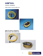
Page 62: ... 62 CONTROL ASSEMBLIES Model Numbers 692 693 and 664 series REMOTE CONTROL ASSEMBLIES Model numbers 882 and 885 series ...

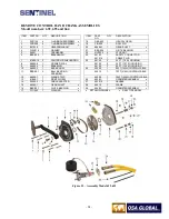
Page 63: ... PLUG 7 81800 10 2 CONTROLCRANK HOUSING 24 59125 2 25 FT 7 6 M HOUSING 8 68900 8 1 CRANK DECAL 59135 2 35 FT 10 7 M HOUSING 9 68900 4 2 BRAKE JAW 59150 2 50 FT 15 2 M HOUSING 10 68900 3 1 BRAKE ARM 25 55005 1 50 FT 15 2M CONTROLCABLE 11 BBS 001 2 BALL BEARING ASSEMBLY 55010 1 70 FT 21 3M CONTROLCABLE 12 68900 7 1 WEAR STRIP 55009 1 100 FT 30 5M CONTROLCABLE 13 81800 1 1 DRIVE WHEEL 26 69303 1 ODOM...

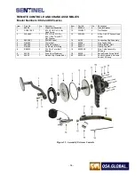
Page 64: ... Thick SST Flat Washer 13 SCR252 6 6 32 x 7 8 SST Socket Head Screw 4 95006 01 1 SAN882 Label 14 66103 1 Connecting Plug Assembly 5 RIN024 1 15mm Seal 15 95039 1 Plug Conduit End 6 95002 6 1 Drive Gear Cover 16 95037 2 1 Clamp Bottom Half 7 RIN026 1 3 x 96 mm ID O Ring 17 95037 1 1 Clamp Top Half 8 BBS032 2 15 x 28 x 7 mm Ball Bearing 18 95050 XX 1 Drive Cable Assembly XX Long 9 95005 1 Drive Gear...

Page 65: ... 65 COMPONENTS FOR Model 664 reel odometer for Model 664 reel Model 692 hand crank Model 693 hand crank Figure 34 Assembly Model 664 ...

Page 66: ...ceed 2 mSv hr 200 mR hr at the surface or 100 µSv hr 10 mR hr at 1 meter 40 inches from the surface when the device is loaded to its maximum capacity 2 Dampen the wipe test swab with EDTA solution Unlock the plunger lock and remove the protective dust cap Wipe the area around the lock mechanism and sealed source connector that protrudes from the lock mechanism 3 Place the wipe test swab in the pla...

Page 67: ...ecipients will provide any specific conditions to the shipper as required by regulatory authorities As a minimum sources that are transferred for a final disposition must be within a current leak test and properly secured within an authorized package before shipment Damaged cropped modified or contaminated source assemblies may require special handling and special transport containers Notify the a...

Page 68: ...sed in connection with this product The use of such material or generators in any manner other than prescribed in the U S Nuclear Regulatory Commission or equivalent Agreement State or permitted by any regulation of the U S Nuclear Regulatory Commission or State Regulation may constitute a violation of such license terms All other warranties except those warranties expressly stated herein includin...

Page 69: ...alarm worn by radiography personnel that provides a continuous audible warning when the alarm ratemeter detects a radiation level in excess of a pre set threshold of 5 mSv hr 500 mR hr This redundant safety alarm is required by regulation for temporary job site radiography within the USA Apparatus for Industrial Gamma Radiography Apparatus including an exposure device a source assembly as applicab...

Page 70: ...ding the source assembly from the radiographic exposure device to the working position having the necessary connections for attachment to the radiographic exposure device and the exposure head or including the exposure head itself The projection sheaths also provide protection of the source assembly and attached control cable from water dirt sand and other foreign materials usually present at radi...

Page 71: ...e where a simulated source is attached to or included with a source holder or control cable this becomes a simulated source assembly Flexible type source assemblies are also known as pigtails The source assembly is most commonly referred to as the source Rigid or chain link type source assemblies are also known as source rods source pencils source trains source chains Source Holder A holder or att...

Page 72: ...lephone 1 781 272 2000 Toll Free 1 800 815 1383 Fax 1 781 273 2216 Email sales sentinelndt com Website www sentinelndt com All goods and services are sold subject to the terms and conditions of QSA Global Inc A copy of these terms and conditions is available upon request SENTINEL is a trademark of QSA Global Inc All brand names and product names where used are acknowledged to be trademarks of thei...

Reviews: