- 50 -
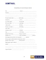
Records of all equipment inspected and maintained during the routine maintenance must be recorded. Records
should indicate:
•
The date of inspection and maintenance.
•
Name and signature of the qualified individual performing the required inspections.
•
Problems found and maintenance or repairs performed.
•
Model number and serial number of the exposure device.
•
Associated equipment that was inspected and maintained.
•
Part numbers and associated lot numbers, or serial numbers of replacement parts installed.
B.
Quarterly Maintenance Requirements – Remote Controls (Crank Out Assemblies)
Disassemble, clean, inspect and maintain the remote control crank, control conduits and control cable according to the
complete, annual maintenance section. Record the results of the inspection and any repairs that are performed. Any
components found to be deficient during the inspection must be removed from service until repaired or replaced. Deficient
components must be labeled with a status indicator to prevent inadvertent use.
C.
Quarterly Inspection of the pneumatic actuator and the air pump control
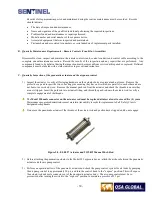
1) Inspect the actuator to verify all fastening hardware on the actuator body are present and not loose. Remove the
protective cap and inspect the two collar ring pins ensuring they have not rotated, are parallel to each other and are
not bent or excessively worn. Remove the manual push rod from the actuator and check the threads to ensure they
are not stripped. Insert the push rod into actuator fitting, and thread the push rod onto the actuator rod to verify a
complete engagement of the threads.
The
Model 550 male connector on the actuator rod must be replaced at intervals
not to exceed five (5) years
.
Maintenance program administrators must maintain traceability records for replacement of all ‘Safety Class A’
designated components
Do not use the pneumatic actuator if the threads of the actuator rod and push rod are stripped, and do not engage.
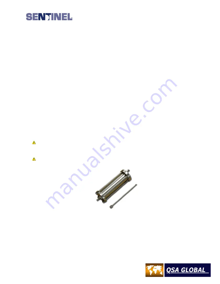
Figure 30 – ELE027 Actuator and TOL012 Manual Push Rod
2)
Before attaching the pneumatic actuator to the Model 989 exposure device, attach the air hose between the pneumatic
actuator and the air pump control.
3) Perform an operational test of the pneumatic actuator and check the pump control system for air leaks by pumping
the air pump control to approximately 30 psi, and turn the control knob to the “expose” position. This will expose
the actuator rod and male connector out of the pneumatic actuator body. The air pump control must be re-
pressurized after turning the switch to the “exposed” position to maintain a pressure of 25 psi.
Summary of Contents for 989
Page 1: ...MAN 037 October 2017 ...


