- 51 -
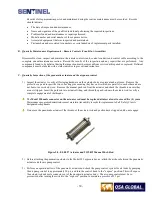
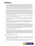
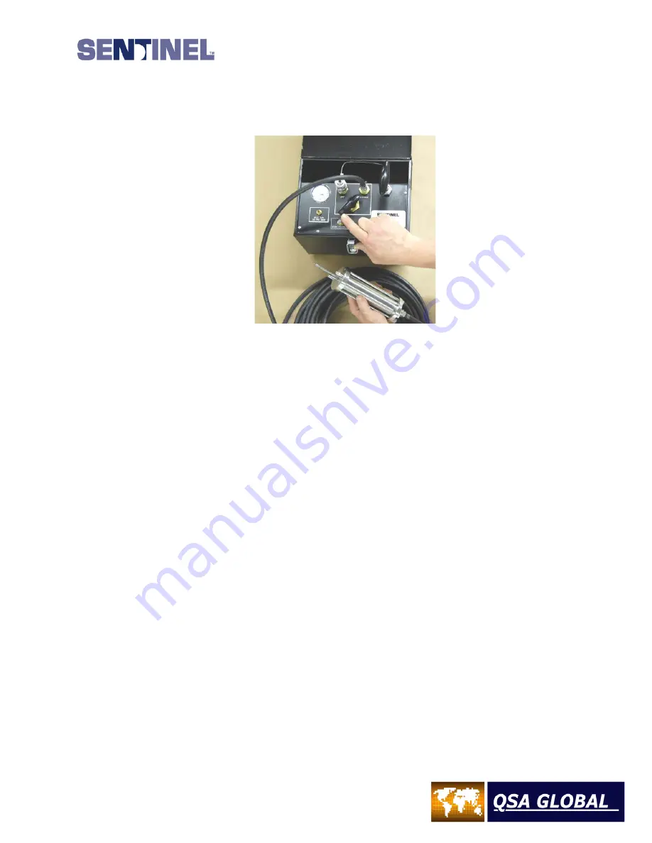
4) Leave the control in the “expose” position for one minute and observe the pressure gage to verify there is no
decrease in air pressure. While the male connector is exposed outside of the actuator body, perform a NO GO gauge
test as described in the daily inspection section. If an air leak is indicated by the pressure gage, check the entire
length of the air hose and all quick-connect fittings. All air leaks must be corrected before use of the system.
Figure 31 – Air Pump Control
5)
Inspect the
pneumatic
actuator rod to ensure it’s clean and free from any corrosion. Examine the male connector for
cracks in the shank, ball and connector body.
6)
After
completing the visual examinations, pressure test and NO GO gauge test, turn the control knob to the “off”
position. Observe the retraction of the actuator rod as it retracts into the actuator body. The actuator movement must
be smooth and continuous. Depress the “zero pressure” valve to completely exhaust the air from the system. A
reading of zero will register on the pressure gauge.
7) Using a soft cloth and mild detergent, clean the exterior and interior of the pump control to remove any dirt and grease
from the control box. Inspect the control box for dents and rust. Press out dents, sand and repaint any areas where
rust is present. Remove retaining screws and remove control faceplate as a unit. Inspect all hoses to ensure they are
in good condition and secured to the fittings and couplers.
8) Inspect the condition of the air reservoir and bleed valve. Clean off components if needed. Install faceplate and
tighten screws. Verify the instruction labels on the control are legible.
9) Verify the control knob and the pump handle are securely attached. Verify the pressure gauge glass lens is not broken
or cracked and is securely attached to the faceplate.
10) Verify the control pump box handle and lock-latch mechanism are securely attached and are functional.
11) Repeat steps 3 and 4 for one minute to ensure the pneumatic actuation system does not have an air leak.
12)
All deficiencies must be corrected before use of the pneumatic pump controls.
D.
Model 989 Exposure Device Annual Maintenance Requirements
The Model 989 exposure device and the pneumatic actuators must receive inspection and maintenance at least once a
year. The pneumatic actuator, locking mechanism and the exposure device must be disassembled for proper cleaning,
inspection and lubrication on components critical to safety and proper function. To accomplish this annual servicing on
the empty exposure device, or to change collimation within the Model 989, the source assembly must be removed and
stored in a shielded cell using specially designed tools.
Summary of Contents for 989
Page 1: ...MAN 037 October 2017 ...

