9
©
All rights reserved. All trademarks are property of their respective owners.
4.
Operation
4.1 General Description
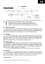
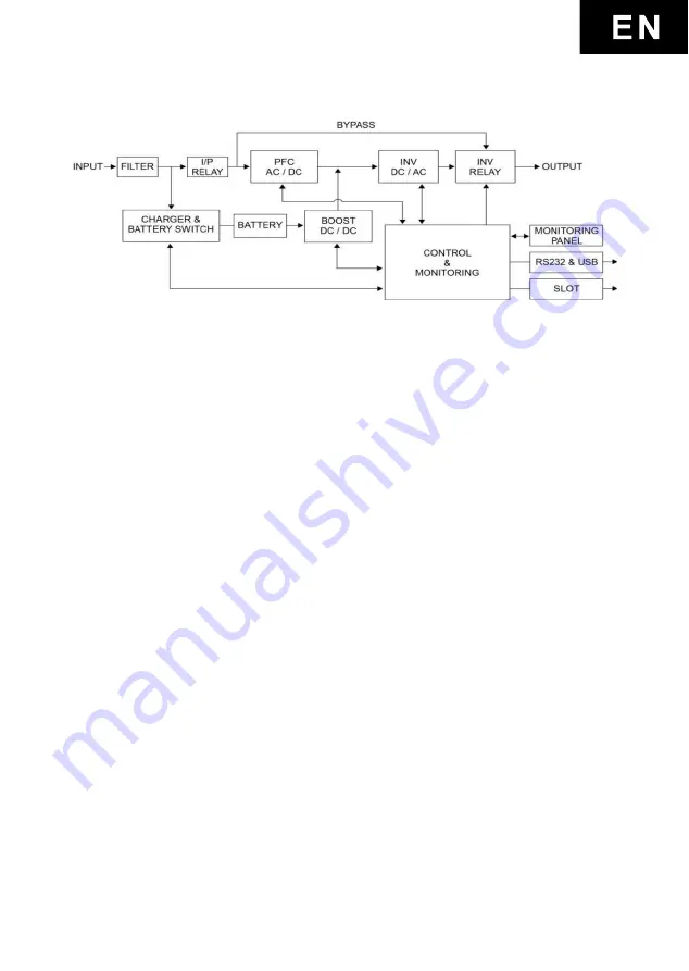
As double conversion On-line UPS, it can convert clean single-phase power to
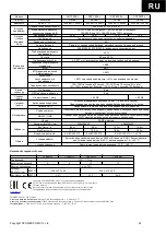
support your critical system. The diagram of UPS is as shown above.
Input filter reduces transients and interference from the main
With PFC AC/DC, AC-power is rectified and regulated to DC power
DC power is converted to AC in the inverter passing it on to the load
Line-Mode/Battery-Mode
UPS will operate in Line-Mode that supports power and charge battery while
connected to power. During a power failure, the UPS will switch to Battery-Mode, in
which power is maintained from the battery. In case of failure time exceed Battery-Mode
duration, UPS will shut down until voltage return to prevent battery discharge.
Free Run Mode
Free Run Mode provides a wider input frequency range when input frequency
does not match the selected range (user adjustable). Free Run Mode enlarges input
frequency acceptance up to 45Hz ~ 65Hz but fixes output frequency to 50Hz(220V) and
60Hz(110V) with ±0.25Hz. Free Run Mode designs for large power variation. It is
activated in default and can run with Line-mode simultaneously.
High-Efficiency Mode
High-Efficiency Mode designs to minimize power loss and power consumption.
Whenever power is stable, UPS will automatically switch to bypass for efficiency. When
any irregularity is detected, Line-Mode will reactivate immediately. Switching occurs
when the input voltage is outside ±10% of nominal (±15% selectable), input frequency is
outside of ±3Hz, or when no input line is available.
You can also activate this mode from the LCD panel. Refer to UPS configuration
.
Diagnostic Test
The diagnostic test automatically executes to check and report UPS status. While
the advanced battery management system monitors the conditions of the batteries, it
sends early warnings if a battery replacement is needed. The test performs every 30
days of normal operation. Diagnostic tests can also activate by manual control.
Generator mode
Summary of Contents for SNT-1000
Page 4: ...Copyright POWERCOM CO Ltd 4 Powercom Co Ltd Sentinel 1 2...
Page 5: ...Copyright POWERCOM CO Ltd 5 40 C 3 5 25 ANSI NFPA 70 26 AWG I 0 15150 69...
Page 6: ...Copyright POWERCOM CO Ltd 6...
Page 7: ...Copyright POWERCOM CO Ltd 7 1 1000 3000 2 2 1 1...
Page 8: ...Copyright POWERCOM CO Ltd 8 RS 232 USB 1 bypass 1 10 15 2 3 3 0 25 50 60 7 2 30 24...
Page 11: ...Copyright POWERCOM CO Ltd 11 5 2 2 1 2 2 2 2 1 2 1 2...
Page 12: ...Copyright POWERCOM CO Ltd 12 5 3 8 3 6 3 Plug Play 5 4 4...
Page 15: ...Copyright POWERCOM CO Ltd 15 7 2 1 3 5 2 20 3 2 10 6 7 3...
Page 16: ...Copyright POWERCOM CO Ltd 16 7 0 24 25 49 50 74 75 100 0 24 25 49 50 74 75 100...
Page 18: ...Copyright POWERCOM CO Ltd 18 7 4 8...
Page 19: ...Copyright POWERCOM CO Ltd 19 9...

