15
©
All rights reserved. All trademarks are property of their respective owners.
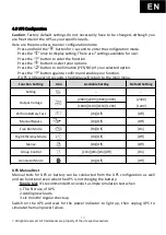
Manual Battery Test: Scroll thought configuration until the Manual Battery test function
displayed. Then select by pressing “Enter” Twice
5.
UPS Monitoring Connection
UPSMON Pro software (Or other power monitoring software) can further utilize the UPS
with warning reminders, monitoring, control shut down, and setting adjustments.
UPS must connect to a computer or the internet to use the monitoring feature.
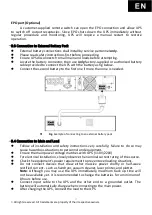
5.1 Connect UPS to Computer with USB (Optional)/RS232 port.
Locate the USB/RS232 port on UPS.
Connect with factory-provided/approved communication cable.
Ensure your computer can install and support power management software.
Note: Either USB Port or RS232 port, only one port will function at a time.
5.2 Connect UPS with interface Slot(Optional)
SNMP Card allows UPS management and monitoring over a network or internet.
For more information, please contact for technical assistance.
5.3 UPS RS232 PORT
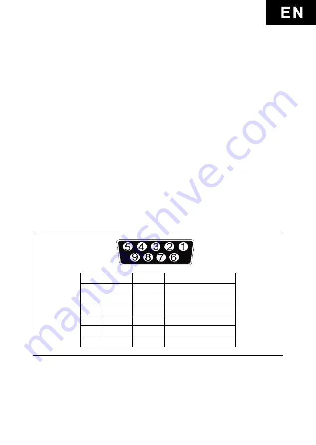
The RS-232 interface uses a 9-pin female D-sub connector.
The RS-232 port carries the data about utility, load, and UPS.
The interface port pins and their functions are in the following table.
Pin #
Signal
Direction
Function
2
TxD
Output
TxD Output
3
RxD
Input
RxD / Inverter Off Input
5
Common
Common
6
Output
AC Fail Output
8
Output
Low Battery Output
9
Output
12VDC Power
Caution! Max rated values 12VDC
5.4 UPS Dry Contact Relay Card
(Optional)
*(0) The Rating of Relay Contacts:
All the Relay Dry Contacts of the Dry Contact Relay Card are rating 1A 24Vdc or 1A 120Vac.
*(1) normally open : NO *(2)Active close : AC
*(3) One of the following conditions activate this signal:
Summary of Contents for SNT-1000
Page 4: ...Copyright POWERCOM CO Ltd 4 Powercom Co Ltd Sentinel 1 2...
Page 5: ...Copyright POWERCOM CO Ltd 5 40 C 3 5 25 ANSI NFPA 70 26 AWG I 0 15150 69...
Page 6: ...Copyright POWERCOM CO Ltd 6...
Page 7: ...Copyright POWERCOM CO Ltd 7 1 1000 3000 2 2 1 1...
Page 8: ...Copyright POWERCOM CO Ltd 8 RS 232 USB 1 bypass 1 10 15 2 3 3 0 25 50 60 7 2 30 24...
Page 11: ...Copyright POWERCOM CO Ltd 11 5 2 2 1 2 2 2 2 1 2 1 2...
Page 12: ...Copyright POWERCOM CO Ltd 12 5 3 8 3 6 3 Plug Play 5 4 4...
Page 15: ...Copyright POWERCOM CO Ltd 15 7 2 1 3 5 2 20 3 2 10 6 7 3...
Page 16: ...Copyright POWERCOM CO Ltd 16 7 0 24 25 49 50 74 75 100 0 24 25 49 50 74 75 100...
Page 18: ...Copyright POWERCOM CO Ltd 18 7 4 8...
Page 19: ...Copyright POWERCOM CO Ltd 19 9...

