background image


10 

5.2.3  Retrieving the pH signal 

After a single or multipoint calibration the AD Converter module the pH value can be read out.  
 
Retrieve pH value 


Send the command bytes: 

999!<CR>


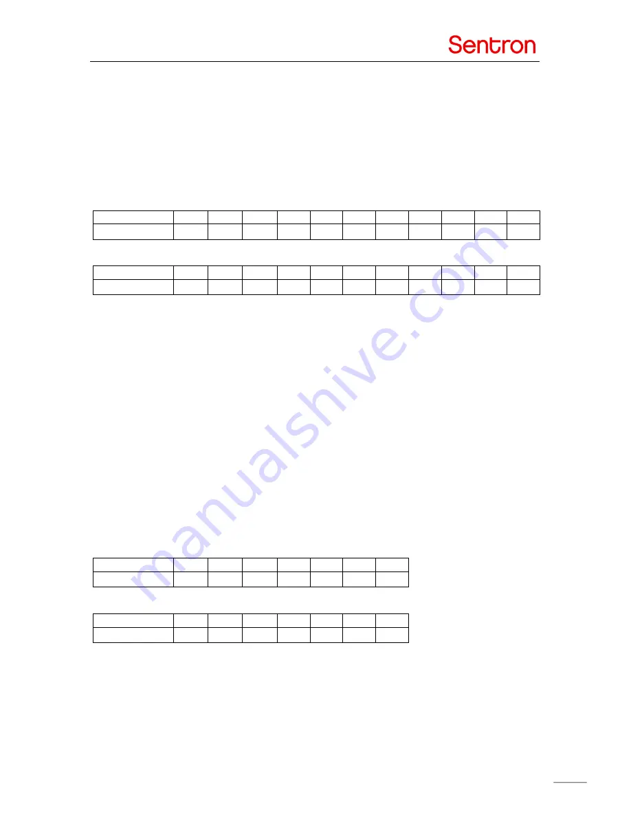
Wait for the module to return the pH value, receive bytes:  ABCDEFGHIJK 

Data ABCDEFGHIJK


 marks the byte position. Values in bytes are needed for decoding. 


Byte position 

Byte value


byte   byte 

byte 

000 

000 

000 

000 

000 

000 

013 

010 

 
Decode received sequence if e.g.: 

Byte position 

Received bytes


001  

023 

027 

000 

00 

000 

000 

000 

000 

013 

010 

 
Protocol: 
A = 

001


B = 

023


C = 

027


DEFGHIJK = n/a 

 
A*4096 + B *64 + C = 1*4096 + 23*64 + 27 = 5595 

pH value = 5.595 


5.2.4  Retrieving the temperature signal 

 
Retrieve temperature value 


Send the command bytes: 

777!<CR>


Wait for the module to return the pH value, receive bytes:  ABCDEFG 

Data ABCDEFG marks the byte position. Values in bytes are needed for decoding. 
 

Byte position 

Byte value


byte   byte 

000 

000 

255 

013 

010 

 
Decode received sequence if e.g.: 

Byte position 

Received bytes


012  

023 

000 

000 

255 

013 

010 

 
Protocol: 
A = 

012


B = 

023


CDEFG = n/a 

 
A*64 + B = 12*64 + 23 = 791 

Temperature value = 79.1 °F  

Summary of Contents for A120-001

Page 1: ...nverter module 4 3 3 USB Interface module 5 Calibration 6 Data communication 7 5 1 Protocol 7 5 2 Examples 8 5 2 1 Performing a single point calibration 8 5 2 2 Performing a multi point calibration 9 5 2 3 Retrieving the pH signal 10 5 2 4 Retrieving the temperature signal 10 5 2 5 Retrieving the slope values 11 5 3 ASCII table 12 E7500347 02 ...

Page 2: ... connects to the Analog front end module and either the standard reference electrode with porous PTFE diaphragm can be used or a suitable custom reference electrode can be attached The AD Converter module can be attached to the Analog front end module This extension module with microprocessor AD Converter and galvanic isolation makes it well suited for use in embedded applications The communicatio...

Page 3: ...3 Specifications ...

Page 4: ... the Analog front end module They are described below 7 Pin 1 pH signal out 52 mV pH pH 7 between 500 and 1800 mV Pin 2 3V3 Power 3V3 DC power power input 100mV Pin 3 AGND Analog Ground Pin 4 PT1000 Directly wired to the PT1000 Pin 5 PT1000 Directly wired to the PT1000 Pin 6 N C Not used Pin 7 Reference External reference electrode connection 3 2 AD Converter module The 6 pin connector of the AD C...

Page 5: ...ognize the USB interface as a USB to COM port converter Windows will install the driver automatically or download the driver from the internet In some cases the driver needs to be installed manually The latest drivers can be downloaded from the FTDI website http www ftdichip com Drivers VCP htm When Windows has installed the driver properly it will assign a COM port number to the USB Interface Thr...

Page 6: ...als The frequency of recalibration is dependent on the conditions the sensor is subjected to and it is recommended to test the calibration at the end of a measurement run to confirm the calibration is still accurate To perform a calibration place the ISFET sensor in the right buffer solution and communicate according the protocol of chapter 5 1 ...

Page 7: ...nd ASCII command bytes Decode calculation Multiply or add decimal byte position value Units A B C D1 E1 F1 G1 H1 I1 J K A 4096 B 64 C 0 001 pH byte byte byte 000 000 000 000 000 000 013 010 A B C 1 D 1 E 1 F G A 64 B 0 1 F byte byte 000 000 255 013 010 Start Calibration CLR CR 067 076 082 033 013 082 013 013 Calibration pH 2 111 CR 5 001 001 001 033 013 001 013 010 2 Calibration pH 4 112 CR 5 001 ...

Page 8: ...2 013 013 The AD converter or USB interface module is now ready to receive the calibration pH 7 command Initiate the pH7 calibration by sending the calibration pH 7 command 113 CR Allow some time for the module to stabilize this may take up to 2 minutes maximum Wait for the module to stabilize receive bytes 003 013 010 End the calibration process send QIT CR Wait for the module to confirm calibrat...

Page 9: ...he module to stabilize receive bytes 002 013 010 Rinse the probe with deionized water Place ISFET sensor and reference in the next calibration buffer solution pH 7 Initiate the pH7 calibration by sending the calibration pH 7 command bytes 113 CR Allow some time for the module to stabilize this may take up to 2 minutes maximum Wait for the module to stabilize receive bytes 003 013 010 Rinse the pro...

Page 10: ...ition A B C D E F G H I J K Received bytes 001 023 027 000 00 000 000 000 000 013 010 Protocol A 001 B 023 C 027 DEFGHIJK n a A 4096 B 64 C 1 4096 23 64 27 5595 pH value 5 595 5 2 4 Retrieving the temperature signal Retrieve temperature value Send the command bytes 777 CR Wait for the module to return the pH value receive bytes ABCDEFG Data ABCDEFG marks the byte position Values in bytes are neede...

Page 11: ... replace the ISFET sensor and or reference electrode Retrieve slope value Send the command bytes 000 CR Wait for the module to return the slope values receive bytes ABCDEFGHIJKLMN Data ABCDEFGHIJKLMN marks the byte position Values in bytes are needed for decoding Byte position A B C D E F G H I J K L M N Byte value 001 byte byte 002 byte byte 003 byte byte 004 byte byte 013 010 Decode received seq...

Page 12: ...12 5 3 ASCII table ...

Reviews: