background image

Appendix B: Verifying/Setting the Operational Voltage 


Vérification/réglage de la tension de service 


Überprüfen/Einstellen der Betriebsspannung


PTPD-VE18 models are equipped with an internal input voltage selector switch, for operation in either 
a 100-120V or a 208-240V environment. 

THIS OPERATION SHOULD ONLY BE PERFORMED BY A QUALIFIED TECHNICIAN. 

The customer is responsible for proper identification of required input voltage and configuration of the Sentry 
Power Distribution Unit. 

The customer assumes responsibility and liability for possible damage to the Sentry Power Distribution Unit, 3

rd


party equipment and/or injury to personnel due to improper configuration.


CETTE OPERATION NE DOIT ETRE FAIRE QUE PAR UN TECHNICIEN QUALIFIE.


Il incombe au client de déterminer correctement la tension d’entrée et la configuration du Sentry Power 
Distribution Unit. 

Le client prend la responsabilité si la Tour Electrique est endommagée, autre équipement/ou blessure de 
personnels à cause d’une configuration incorrecte.


DIESE ARBEITEN SOLLTEN NUR VON EINEM QUALIFIZIERTEN TECHNIKER DURCHGEFÜHRT 
WERDEN. 

Der Kunde ist für die Ermittlung der erforderlichen Eingangsspannung und die Konfiguration des Sentry Power 
Distribution Unit verantwortlich. 

Der Kunde die Verantwortung und Haftung für eine etwaige Beschädigung des Sentry Power Distribution Unit, 
der Ausrüstung von Fremdfirmen und/oder Verletzungen von Mitarbeitern durch Falsche Konfiguration. 

Tools needed: 
1. Philips 

screwdriver 

Outils nécessaires: 
1. Tournevis 

cruciforme 

Benötigtes Werkzeug Teile: 
1. Kreuzschlitzschraubenzieher
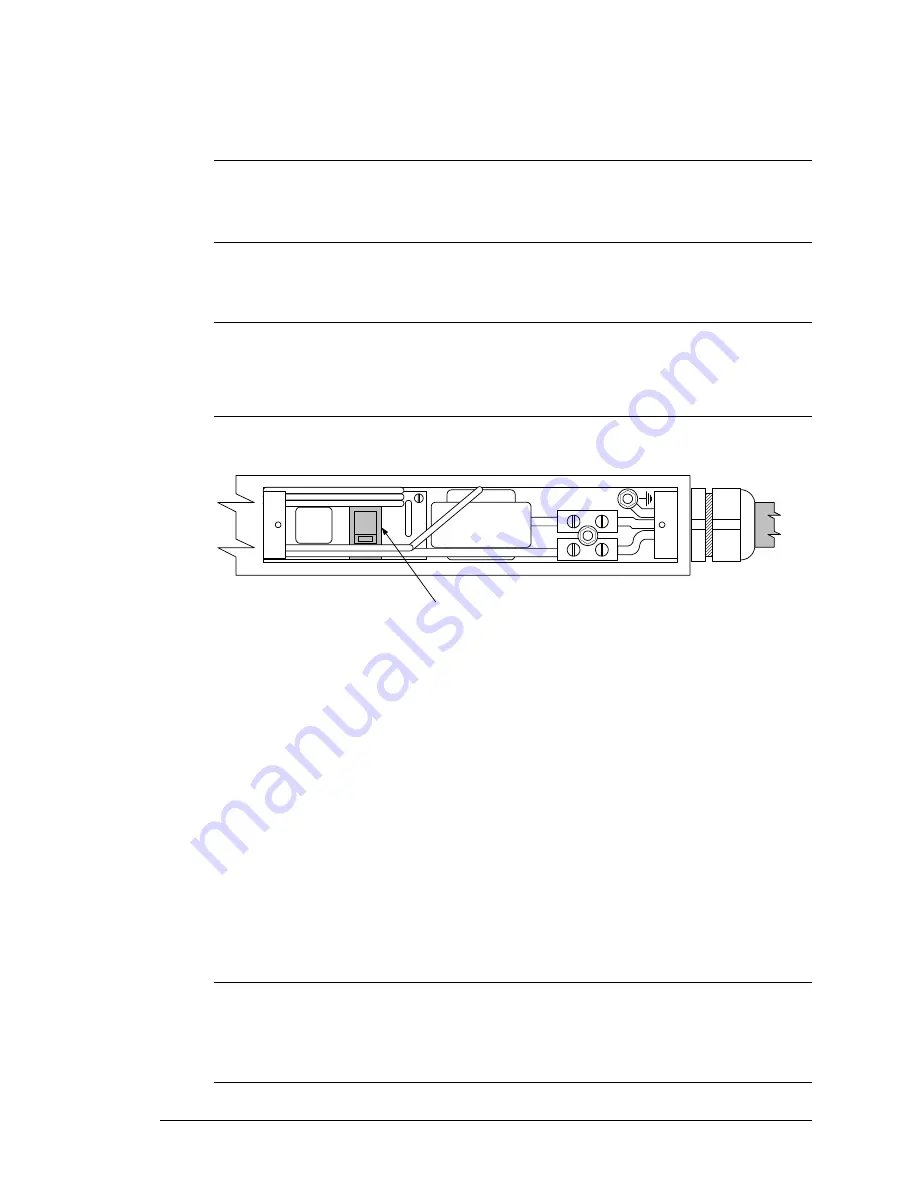
230V

Voltage selector switch

Sélecteur de tension

Spannungswahlschalter

Procedure: 
1. 

Unplug Sentry Power 
Distribution Unit. 

2. 

Open the rear access plate. 

2.1.  Remove both screws from 

access plate on the back of 
the Sentry Power 
Distribution Unit. 

2.2.  Remove the access plate. 

3. 

Verify the proper setting on the 
voltage selector switch.  
Correct as necessary. 
115V – for 100-120V 
230V – for 208-240V 

4. 

Replace rear access plate and 
secure with original screws. 

Procédure: 
1. 

Débrancher la Sentry Power 
Distribution Unit. 

2. 

Ouvrir la plaque d’accès de 
dernière. 

2.1.  Enlever les deux vis de la 

plaque d’accès dernière la 
Power Twoer. 

2.2.  Enlever la plaque d’accès. 

3. 

Vérifier que le sélecteur de 
tension est correctement 
positionné. Changer le réglage 
selon le besoin.   
115V – pour 100 -120V 
230V – pour 208-240V 

4. 

Remettre la plaque de dernière 
et fermer bien avec les vis 
original. 

Vorgangsweise: 
1. 

Ziehen Sie den Stecker des 
Sentry Power Distribution 
Unit heraus. 

2. 

Öffnen Sie die hintere 
Abdeckung. 

2.1.  Entfernen Sie beide 

Schrauben aus der 
hinteren Abdeckung des 
Sentry Power Distribution 
Unit. 

2.2.  Nehmen Sie die 

Abdeckung ab. 

3. 

Vergewissern Sie sich, dass 
der Spannungswahlschalter 
richtig eingestellt ist. Ändern 
Sie die Einstellung bei 
Bedarf. 
115V - für 100 - 120 V 
230V - für 208 - 240 V 

4. 

Bringen Sie die hintere 
Abdeckung wieder an, und 
befestigen Sie sie mit den 
Originalschrauben. 

NOTE:   
Changing the voltage setting of the Sentry Power Distribution Unit may require changing of the input power cord.  For 
information on changing the input power cord, go to www.servertech.com. 

Le changement du réglage de tension du Sentry Power Distribution Unit peur exiger le changement du cordon 
d’alimentation. Pour toute information concernant le changement du cordon, consulter le site  www.servertech.com.


Bei einer Änderung der Spannungseinstellung des Sentry Power Distribution Unit muss unter Umständen das Netzkabel 
ausgetauscht werden. Informationen über den Austausch des Netzkabels finden Sie unter www.servertech.com. 

Sentry Power Tower Power Distribution Unit 

Appendices 


15


Installation and Operations Manual 


Verifying/Setting the Operational Voltage 


Summary of Contents for PTPD-H0

Page 1: ...Sentry AC Power Distribution Unit PTPD V0 PTPD H0 PTPD VE PTPD HE Installation and Operations Manual...

Page 2: ...alysis systems peritoneal dialysis systems neonatal ventilator incubators ventilators for adults or infants anesthesia ventilators infusion pumps and any other devices designated as critical by the U...

Page 3: ...Mounting 6 Connecting to the Power Source 6 Connecting Devices to the PTPD 7 Connecting to the PTPD PTPD x0 models only 7 CHAPTER 3 OPERATIONS PTPD X0 MODELS ONLY 9 Interface 10 Displaying the Contro...

Page 4: ......

Page 5: ...Chapter 1 Introduction FEATURES AND BENEFITS 2 Power Distribution 2 Load Measurement 2 Over Threshold Notification 2 Technical Support 2 QUICK START GUIDE 2...

Page 6: ...PD xE models Over Threshold Notification Sentry Power Distribution Units features two standard over threshold alarms an audible alarm for the local technician and a contact closure alarm circuit which...

Page 7: ...ITEMS 4 EQUIPMENT OVERVIEW 4 SAFETY PRECAUTIONS 5 VERIFY INPUT VOLTAGE SELECTION PTPD VE18 MODELS ONLY 5 MOUNTING 6 Horizontal Rack PTPD 6 Vertical PTPD 6 CONNECTING TO THE POWER SOURCE 6 CONNECTING D...

Page 8: ...ough A4 B1 through B4 C1 through C4 and D1through D4 The power inlet of the PTPD connects the PTPD to the electrical power source See Appendix C Technical Specifications for more information Ports Inp...

Page 9: ...wer supply cord shall be installed near the equipment and shall be easily accessible La prise sur le cordon d alimentation sera install e pr s de l quipement et sera facilement disponible Der Stecker...

Page 10: ...es Representative for information regarding custom bracket design and fabrication services if you are unable to find a suitable manner for utilizing the included mounting brackets Connecting to the Po...

Page 11: ...esigned for use with Server Technology s IEC 60320 C13 to IEC 60320 C14 cable CAB 1302 The retention clip may not properly fit 3rd party cables Always disconnect the power supply cord before opening t...

Page 12: ......

Page 13: ...reen 10 USING THE CONTROL SCREEN 10 Location field 10 To specify a location 10 Input Current field 10 Threshold field 10 To adjust the overload threshold 10 Alarm Status field 11 Clearing an Over Thre...

Page 14: ...ocation field T Pressing T allows editing of the overload threshold Enter Displays or refreshes the Control Screen The following sections describe each Control Screen field Location field The editable...

Page 15: ...rrent returns to 1 8 ampere below the overload threshold To clear an alarm from the Control Screen Type c To clear an alarm using the reset button On the front of the PTPD locate the recessed reset bu...

Page 16: ......

Page 17: ...TIONAL VOLTAGE 15 APPENDIX C TECHNICAL SPECIFICATIONS 16 Standard Models 16 Ratings 17 Fuses 17 Data Connection PTPD x0 models only 18 RJ45 to DB9F serial port adapter 18 IDC10 alarm port 19 APPENDIX...

Page 18: ...eset button directly below the Input Current LED You will need a non conductive non metallic tool that fits inside the recess Insert the tool in the recess then depress and hold the reset button for a...

Page 19: ...crews from access plate on the back of the Sentry Power Distribution Unit 2 2 Remove the access plate 3 Verify the proper setting on the voltage selector switch Correct as necessary 115V for 100 120V...

Page 20: ...red NEMA 5 15P 15A 125V straight 18 IEC 60320 C13 PTPD VE18 0 04 100 240V 50 60Hz Hardwired NEMA L5 20P 20A 125V locking 18 IEC 60320 C13 PTPD VE18 0 05 100 240V 50 60Hz Hardwired NEMA L5 30P 30A 125V...

Page 21: ...D4 or 9 10 11 12 13 14 15 16 5 1 2 3 4 5 6 OR 7 8 9 10 11 12 OR 13 14 15 16 17 18 Les configurations suivantes NE SONT PAS disponible Unit s de 100 120V avec indice de courant d entr e de 16A Unit s d...

Page 22: ...an RJ45 RS 232c serial port This connector may be used for direct local access or from other serial devices such as a terminal server An RJ45 crossover cable is provided for connection to an RJ45 DTE...

Page 23: ...The relay switches to close the circuit in response to an over threshold alarm Normally Closed The relay switches to open the circuit in response to an over threshold alarm 2 Relay specifications Manu...

Page 24: ...strict compliance with Server Technology s operation and installation manual c has become defective or inoperative due to its integration or assembly with any equipment or products not supplied by Ser...

Page 25: ...irs Server Technology shall assume return shipping charges but for non warranty repairs the shipping charges shall be billed 3 The RMA shall be placed conspicuously on all shipping documentation assoc...

Page 26: ...a 89521 775 284 2000 Fax 775 284 2065 E mail sales servertech com World Wide Web www servertech com Sentry and Sentry Power Distribution Unit are trademarks of Server Technology Inc 301 0121 1 Rev C 0...

Reviews: