Fold Here
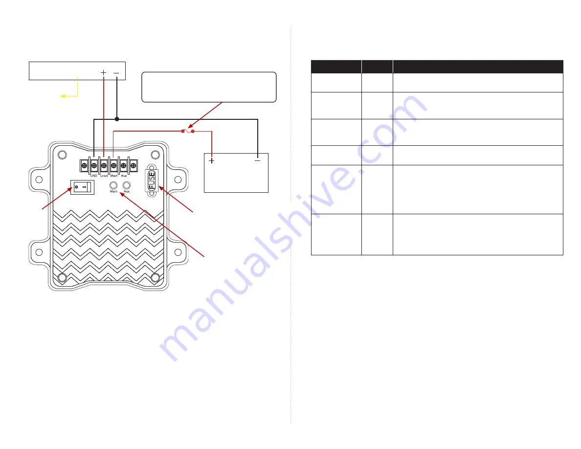
Wiring Diagram
Vehicle Battery
(12V DC nominal)
IGNITION
To vehicle
switched 12V
Black
Red
Yellow
Black
Red
Power switch
Fuse holder
Setpoints
The UPS ships configured with the following setpoints:
Setpoint
Voltage
Description
Main On
12.5V
When the voltage from the vehicle battery is greater than 12.5V,
the controller uses vehicle battery power for the recorder.
Main Off
11.8V
When the voltage from the vehicle battery is less than 11.8V, the
controller switches the recorder from vehicle battery power to
UPS battery power.
Charge On
12.7V
When vehicle battery power is above 12.7V, the controller sends
a trickle charge to the UPS battery. This charging operation is
independent of the other functions.
Charge Off
12.1V
The controller stops charging the UPS battery when voltage
from the vehicle battery falls below 12.1V.
Aux On
*
12.6V
If voltage from the vehicle battery is below 11.8V (Main Off), the
unit switches the recorder to the auxiliary battery, independent
of the value of Aux On. Once the auxiliary battery has dropped
below 10.0V (Aux Off), it stays off until the vehicle battery
power is above 12.5V (Main On). The Aux On feature powers the
recorder if the auxiliary battery is replaced or charged.
Aux Off
*
10.0V
When the voltage at the Aux Input is less than 10.0V, the Aux
Input is disconnected. It is not reconnected until the voltage
at the Aux Input is greater than 12.6V (Aux On). If the vehicle
battery voltage comes back, the controller switches the recorder
power to the vehicle battery and resets the Aux On/Off state.
*
Auxiliary battery is optional
.
LED Indicators
When illuminated, LEDs indicate which source (vehicle battery or UPS internal battery) is powering
the load, as follows:
• Main
- vehicle battery is powering the recorder
• Aux
- UPS internal battery is powering the recorder
LED indicators
Minimum gauge: 14 AWG
Minimum gauge: 14 AWG
Wire the main power fuse/holder from
the recorder power harness kit between
the vehicle battery and the UPS
UPS
Recorder
Installing the UPS
1. Choose a mounting location according to the
Installation Requirements
on page 1.
2.
Use 4 self-tapping screws (not supplied) to secure the UPS to the mounting surface.
3. Wire the UPS to the vehicle battery and the recorder as shown in the Wiring Diagram.
4.
Remove the plastic fuse cover by snapping it off its base.
a.
Insert the supplied 15A fuse into the fuse holder.
b. Snap the fuse cover back into place.
5.
Power on the device.


