15
15
AsteRx-i3 D OEM & AsteRx-i3 S OEM
15
2.8
Frequency Reference Output (REF OUT)
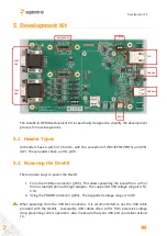
The frequency reference used by the receiver is available at the REFOUT u.FL connector.
This is a 10MHz square wave, 0 - 2.8V, output impedance 50Ohms.
2.9
Event/TimeSync Inputs
The receiver features two event inputs (EventA on the 30-pin connector, and EventB on
the 60-pin connector), which can be used to time tag external events with a time resolution
of 20ns. Use the
setEventParameters
command to configure these pins (e.g. to set the
polarity). Note that this feature requires the TimedEvent permission to be enabled in the
receiver.
2.10
General Purpose Output (GPx)
The GP1 and GP2 pins of the 60-pin connector are general purpose LVTTL digital outputs,
of which the level can be programmed with the
setGPIOFunctionality
command.
During the first seconds after powering up the board, these pins are in tristate. Use an
external pull-down or pull-up resistor to have the desired level during boot.
The GPx pins can drive a maximum current of 10mA.
2.11
Standby Mode
In standby mode, all receiver functions are turned off and the power consumption is
significantly reduced (see section 2.5). There are two ways to enter standby mode:
1.
By driving the nPDN pin low (pin#20 of the 30-pin connector). The receiver wakes
up when the nPDN pin level is high again (there is an internal pull-up).
2.
By entering the “
exePowerMode, StandBy
”
user command. To wake up, the nPDN
pin should be shortly driven low (at least for 50ms).
It is also possible to schedule automatic standby/wakeup periods using the
setWakeUpInterval
command.
REF OUT


