16
16
AsteRx-i3 D OEM & AsteRx-i3 S OEM
16
Note that entering standby mode takes a few seconds during which all running processes
are shutdown.
Warning:
Do not drive a non-zero voltage into input pins
(pins type “I”)
when the receiver
is in standby. To be safe during standby, it is recommended to use the IO_EN signal of the
60-pin connector as enable for the drivers driving the input pins. The IO_EN signal is low
during standby.
2.12
SD Memory Card Usage
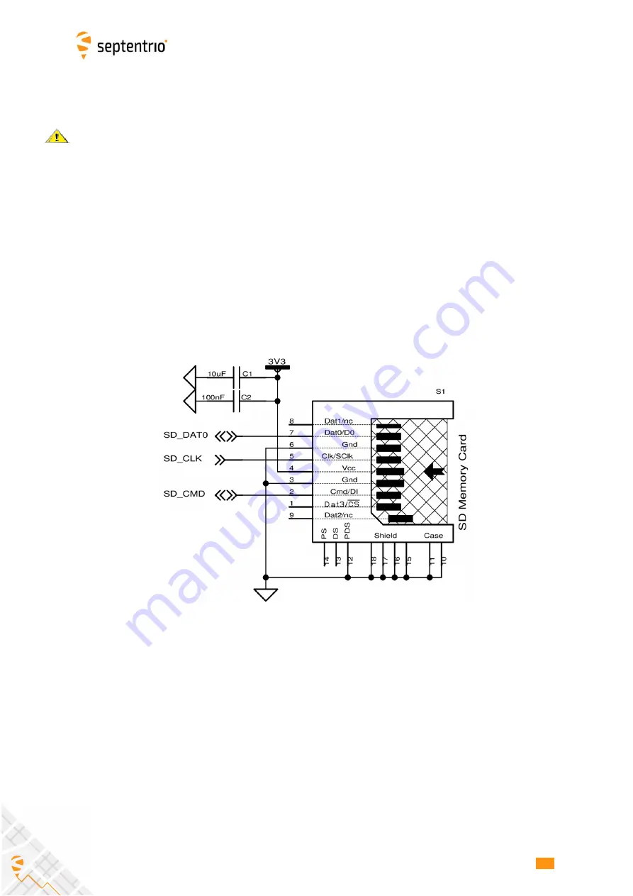
The receiver can interface to an external SD memory card through the SD-card pins of the
30-pin connector. The receiver supports the 1-bit SD transfer mode with 3V3 signaling.
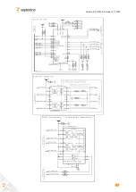
An example circuit to a 9-pin SD memory card socket is shown below. The maximum clock
frequency (SD_CLK) is 33.000 MHz.
See instructions in the Reference Guide for details on how to configure SD card logging.
The receiver is compatible with SD cards of up to 32GB. The file system is FAT32.
Shortly driving the button pin (pin#25 of 30-pin connector) low toggles logging on and off.
Driving the button pin low for at least 5 seconds unmounts the SD card if it was mounted,
or mounts it if it was unmounted. The SD card mount status can be checked with the
LOGLED pin (see Appendix A).
When powering off the receiver while logging is ongoing, it can be that the last seconds of
data are lost. To avoid data losses, it is advised to first unmount the SD card. This can be
done in two ways:


