


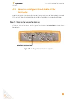
4.1. HOW TO CONFIGURE THE ASTERX-U FOR RTK
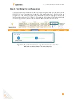
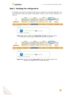
Step 3: Verifying the configuration
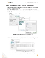
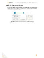
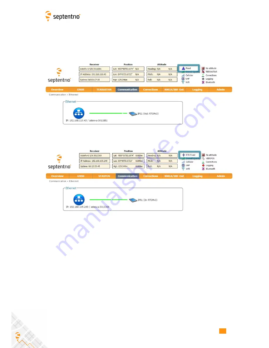
If the Base station and rover receivers have been configured correctly then graphics in the
Communication Ethernet windows should appear similar to those shown in Figures 4-13
and 4-14.
Figure 4-13:
Ethernet window of the
Base station receiver
showing the position
as static and an active output of RTCMv3 diff corr on server port IPS1
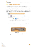
Figure 4-14:
Ethernet tab of the
rover receiver
showing a fixed RTK position and
reception of RTCMv3 diff corr on receiver port IPR1
41
Summary of Contents for AsteRx-U
Page 1: ...AsteRx U User Manual ...