background image

Summary of Contents for prophet 5

Page 1: ...pRophet TECHNICAL MANUAL EOUEnUiAL ci cuici nc ...

Page 2: ... thoroughly with this manual before attempting any work on the Prophet This will at least help you judge whether you should be working on it at all If in doubt please contact our Service Department The manual is organized as follows SECTION 1 describes the Prophet s physical organization and procedure for its complete disassembly SECTION 2 covers principles of the system hardware and software desi...

Page 3: ...HET 5 SYNTHESIZER TECHNICAL MANUAL By STANLEY JUNGLEIB Wine Country Productions Inc 1572 Park Crest Court Su4e 505 San Jose CaWomia 95110 USA pnooe 408 265 2008 PAX 408 266 6591 SEQUENTIAL Product Soecw sTs Since 1987 ...

Page 4: ...ry 1980 Copyright 1980 by SEQUENTIAL CIRCUITS INC All rights reserved Printed in USA The contents o this manual are the property of SCI and are not to be copied or reproduced in any whatsoever without our prior written permission manner ...

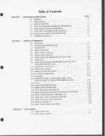
Page 5: ...TER FILT 2 8 AMPLIFIER ENVELOPE GENERATOR AMP ENV GEN AND AMPLIFIER FIN 2 9 AUDIO OUT AUD OUT 2 10 COMMON ANALOG 2 11 MICROCOMPUTER SYSTEM 2 12 CV AND S GENERATION 2 13 MATRICES 2 14 POTENTIOMETER MULTIPLEXER POT MUX AND ANALOG TO DIGITAL CONVERSION ADC 2 15 TUNE 2 16 HARDWARE DESCRIPTION 2 17 BD001 INTERCONNECTION 2 18 SD211 CONTROL PANEL POTS 2 19 SD212 CONTROL PANEL SWITCH AND LED MATRICES 2 20...

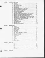
Page 6: ... ENVELOPE AMOUNT VCA BALANCE 4 7 4 14 R405 POLY MOD OSCILLATOR B AMOUNT VCA BALANCE _4 7 4 15 R413 OSCILLATOR B TRIANGLE SYMMETRY 4 8 4 16 R415 FINAL VCA BALANCE 4 8 4 17 FILTER TUNING 4 8 4 18 OSCILLATOR TUNING 4 9 4 19 R416 VOICE LEVEL 4 13 4 20 R303 SEQUENCER CV OFFSET 4 13 SECTION S SERVICE NOTES 5 0 GENERAL 5 1 5 1 POT MUX ADC 5 1 5 2 KEYBOARD KBD 5 1 5 3 SWITCH MATRIX 5 1 5 4 LED MATRIX 5 2 ...

Page 7: ... as covered in this section 1 1 PRECAUTIONS Observe the following precautions when working on the Prophet To prevent damage to the top panel keyboarder woodwork use a carpetted or similarly covered work surface when opening the cabinet Set S701 power switch OFF and check S702 115 230V on the back panel of units 184 and above before connecting to power outlet Never switch line voltage with instrume...

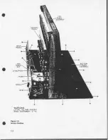
Page 8: ...TOP PANEL ASSEMBLY l CONTROL PANEL BACK PANEL BOTTOM PANEL ASSEMBLY J709 P402 PCB6 WARNING LETHAL VOLTAGE PRESENT WHEN INSTRUMENT IS ON Figure 1 0 Service Position 2 ...

Page 9: ...lide the top panel assembly forward about six inches so when raised the control panel knobs will dear the power supply capacitors Raise the top panel assembly to service position shown in Figures 1 0 and 1 1 For best stability both top panel side back edges should rest on the bottom panel The top panel upper edge rests on a cable from the back panel This is normal but a small half inch prop may be...

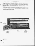
Page 10: ...ain the audio output cable which connects to the back panel Power may be switched back on in this con figuration To remove PCB 4 completely switch power off and disconnect voice power cable at PCB 3 Figure 7 7 Also remove W703 with a gentle see saw motion at P303 Then detach audio output cable at quick disconnects J709 P402 on back panel 1701 AUDIO OUT Figure 7 0 When reconnecting voice power cabl...

Page 11: ...d pull at the standoff indicated also using a see saw motion to mini mize stress along the board When replacing PCB 3 be sure J301 P201 pins are correctly mated before fastening screws Align ment is insured by matching screw holes with their standoffs Remember to reconnect the wheel cable too before replacing PCB 4 When reconnecting back panel cable be sure tabs interlock J30I STANDOFF WHEEL BACK ...

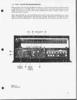
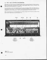
Page 12: ...d removing both panels by taking advantage of W701 the rlexible intercon nect between them Figure 1 4 Also Section 3 of this manual includes pictorials identifying panel components from the solder side that is as the control panels are normally mounted When replacing be sure all potentiometers fit correctly through the front panel and check switch action before tightening any potentiometer nut W70...

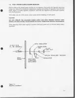
Page 13: ...e back panel After repair you can check power supply output before installing on back panel CAUTION DO NOT OPERATE THE UNLOADED POWER SUPPLY FOR LONG PERIODS WITHOUT HEAT SINKING THE REGULATORS NEVER OPERATE THE SUPPLY UNDER LOAD WITHOUT HEAT SINKING When replacing PCB 6 check regulator insulation from back panel with an ohmeter before apply ing power 4 40 X 3 8 FL HD SCREW innoo BACK PANEL MICA I...

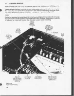
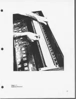
Page 14: ...rd will slide out of the case and back in as shown in Figure 7 7 NOTE During this operation the wires Figure 1 6 for the lowest and highest keys are vulnerable to damage through collision with the keyboard mounting brackets When replacing check J wues at each end of keyboard for contact with bus bar Also remember to attach wheel ground lug R702 MOD WHEEL FRONT KEYBOARD MOUNTING SCREW R70I PITCH WH...

Page 15: ...Figure 1 7 Keyboard Removal 1 9 ...

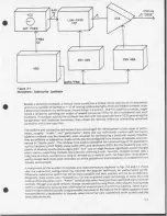
Page 16: ...Figure 2 0 Monophonic Additive Synthesis 2 2 ...

Page 17: ... pulse width PW and resonance RES But the flexibility and com plexity of modular synths discourages their live use on stage because significant sound changes often require repatching modules and precisely checking knobs Favorite comp ex sounds take a long time to create and almost as long to recreate on a modular synth So these often monophonic synths instead feed multi track recorders on which po...

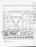
Page 18: ...ices their outputs are combined and overall volume set by a VCA controlled directly from the front panel Each voice is a complete synth with two VCOs a MIXER VCF FINAL VCA and two ENV GENs but they are patched homophonously by common switch S signals and CVs Each voice also has its own KEY CV which provides polyphonic pitch information and GATE which signals that the key is being held All S signal...

Page 19: ...COM ANAL uxuvwwumuwvMvv Figure 2 3 Prophet 5 Functional Diagram ...

Page 20: ...2 S 2 6 ...

Page 21: ... for OSC 1 and 2 marked on the control panel Also the terms OSC and VCO FILT and VCF AMP and FIN VCA are used interchangeably Fig 2 4 diagrams a single voice and should be referred to for paragraphs 2 4 through 2 9 below Four types of functions are shown 1 VC modules OSC A OSC B VCF FIN VCA and the FILT and AMP ENV GENs 2 CV summers SMRs which combine the various CVs for OSC FREQ or PW or FILT FRE...

Page 22: ...t OSC B PW is unaffected by P MOD so a summer equivalent to the A PW SMR is not required PW B CV results from PW B INIT CV and PW B W MOD CV combined in the PW B MSUM OSC B has a bipolar triangle wave output in addition to the positive going sawtooth and pulse outputs The P MOD OSC B AMT VCA sets CV level to the destinations selected by the three P MOD switches 2 6 FILTER ENVELOPE GENERATOR FILT E...

Page 23: ......

Page 24: ...FROM OTHER 2 9 ...

Page 25: ......

Page 26: ...OSCA MSUM 1 2 10 ...

Page 27: ...ulation of the VOICES ASUM CV the common OSC A frequency CV consists mainly of the OSC AINIT CV which follows the OSC A FREQ control The P BND or MTUN controls effect pitch adjustment When in UNISON mode the indi vidual voice KEY CVs are switched off and UNISON UNI CV follows the keyboard Increased GLIDE CV delays quick changes in UNI CV W MOD output is added to A SUM CV when the W MOD FREQ A swit...

Page 28: ...d addresses on those busses and activates the IOREQ and WR signals This produces CSS from the OUT PORT DCOD which latches the data into the keyboard switch and LED matrices The matrix converts digitizes key strokes into binary data The address changes IOREQ and this time RD are activated This produces CSE from the IN PORT DCOD driving matrix data representing the key held on to the bus The CPU per...

Page 29: ......

Page 30: ... r VDAC CV Jl n DMUX 17U INDIVIDUAL VOICE CVs COMMON CVs CV DMUX ADDRESSES TO COMMON ANALOG ANO VOICES SWITCH S COMMANDS GATES GRAM MER FROM PROGRAMMABLE ITCHES BLACK SWITCHES TO LED INDICATORS 2 15 ...

Page 31: ...rent addition performed by the ladder is shown The exact DAC scaling is 1 12V 83 3 mV per step This was chosen for convenience in controlling the OSC and FILT FREQs which are scaled at IV octave With these values each step results in a fre quency change of exactly one semitone Which is why the OSC FREQ knobs adjust in semitones The 7 bit DAC has a range of 128 steps thus 0 10 583V 127 X 1 12V In a...

Page 32: ......

Page 33: ...the row are held will place 1 on their connecting columns DY0 DY7 For example if DO is held the number 00000100 will be driven on to the bus when CSE appears If more than one key in a row is held the CPU subtracts to find the actual combination After reading row DX0 the CPU activates row DX1 with the number 00000010 and CS8 and reads the matrix output again with CSE The matrix diodes prevent switc...

Page 34: ......

Page 35: ...ampled are latched off of the DATA BUS by U210 when clocked with CSA from the OUT PORT DCOD The ST CONV signal latched elsewhere in the computer tells the ADC to start converting VMUX Inside the ADC a binary counter increments until an external comparator finds its analog equivalent equal to VMUX The comparison stops the counter and sends END CONV to the interrupt INT pin of the CPU The IN PORT DC...

Page 36: ...illator pitch any can detune them Additionally each OSC also has a V OCT and a HI V OCT trimmer which affects the tuning Finally any 2030 VCO can be different enough from the others to be out of tune They age and their pitch is affected by temperature although this effect is reduced with temperature compensating resistors There are two basic parameters to work with in tuning One is initial frequen...

Page 37: ... total Now when playing the computer determines the pitch each oscillator is to sound and continually corrects by applying one of the four biases It uses the 300 Hz BIAS up to about 450 Hz where the 600 Hz BIAS takes over The 1200 Hz BIAS CV is used between about 900 1800 Hz and 2400 Hz BIAS CV corrects the rest of the frequency range 2 16 HARDWARE DESCRIPTION The remainder of this section comment...

Page 38: ...is R104 MASTER TUNE MTUN programmable Also a silver colored knob It offsets the OSC A and B MASTER SUMMERS MSUMs allowing over a semitone of flat or sharp correction The MTUN signal is summed with other pitch changing signals by U365 7 The remainder of the pots are wired to the POT MUX those on PCB1 through TB101 W701 and TB201 TABLE 2 0 shows the data latched by U210 to select each pot The bits Q...

Page 39: ...e that three control switches are wired in the keyboard matrix This is no problem The computer knows that any number read from DX7 larger than 31H must include one of these switch operations The control switches are read in similar fashion with CSE from the IN PORT DCOD except SI 12 EDIT and S113 TUNE each drive two columns Separately clocked sections of the U204 5 BUS DRIVERS are paralleled for h...

Page 40: ...cted by CSs from U323 25 26 IN and OUT PORT DCODs U323 ANDs RD with A0 A2 U324 ANDs WR with A3 A5 U32S shifts logic levels to clock high voltage CMOS latches U357 63 56 61 62 60 U355 similarly shifts DATA BUS levels for these latches High voltage latches are required to control analog switches which must pass 10 V level waveforms Current limiting resistors such as R3140 41 42 are installed whereve...

Page 41: ...s the CPU to fetch the counter value through the bus drivers In more detail to convert a POT value the CPU issues ST CONV to U321 4 U321 6 goes low reset ting U334 s internal counter and setting status latch U333 1 U333 3 goes high enabling U333 6 GATED CLOCK The GATED CLOCK strobes U334 4 at about 500 kHz incrementing the binary counter U334 14 ANA OUT is a ramp which lengthens with higher pot se...

Page 42: ...R109 REL 4 R106 FILT ATK 2 R107 R108 DEC 2 S SUS 3 ATK 3 DEC 6 SUS 5 REL 9 U334 14 V 200 mV div H 2 ms div x10 MAG Waveform 2 1 FOUR POT CONVERSIONS ...

Page 43: ...stage consists of simple op amp summers and BIFET buffers connected through pre cision matched resistors The GLIDE circuit active only in UNISON mode consists of Q309 exponential converter U379 trans conductance amplifier C348 and U378 1 BIFET buffer Increased GLIDE CV delays the effectiveness of rapid UNI CV changes U379 is wired for unity gain through U378 1 so its voltage output GLIDE OUT CV sh...

Page 44: ...rimming by R303 U416 TUN MUX LEVEL COMPARATOR output goes negative for the period the 10 V oscillator saw tooth is below the 1 5 V threshold see Figure 2 10 R4134 in series with U496 AUD DRVR minimizes effects of capacative loads R4137 reduces hum resulting when the Prophet is switched off but left connected to an energized amplifier 2 23 SD411 415 VOICES 1 5 The following refers primarily to SD41...

Page 45: ...tion in the control circuit Variable width pulse output is derived by internally comparing the sawtooth to the pulse width input pin 9 Control sensitivity is 10 V 100 5 0V decreasing to0 at 10V Pulse output Is0 7 5V across pull down R454 or R443 When switched on OSC A s HARD SYNC input pin 7 senses OSC B s saw tooth edge forcing immediate discharge The sawtooth and psuedo triangle output pins are ...

Page 46: ......

Page 47: ...or dc offset and CV leakage rejection The FILT and AMP ENV U406 U401 GENs are based on the SSM 2050 ENV GEN see figure 2 14 Elec Ironically switched CVs charge and discharge C418 C419 through an exponential voltage controlled resistor The ADSR states are defined by internal logic clocked from the GATE and TRG inputs An ATK flip flop FF is set by the TRIG pulse through C402 C401 and reset by either...

Page 48: ...ANALOG SWITCHES CAP ...

Page 49: ... AND PCB6 This diagram is straightforward T701 s secondary is rated at 2 8A U601 U603 and U60S are rated at 1 5A U602 is rated at 350 mA U605 at 500 mA 1702 1708 are grounded to the power line through the bottom panel 2 32 ...

Page 50: ...Hs AUD OUT PA 416 PCB 4 TRIMMERS and OSC SAWTEETH PA411 VOICE 1 SD411 VOICE 1 PA412 VOICE 2 SD412 VOICE 2 PA413 VOICE 3 SD413 VOICE 3 PA 414 VOICE 4 SD414 VOICE 4 PA 415 VOICE 5 SD415 VOICE 5 PA 610 PCB 6 SD711 BACK PANEL AND PCB 6 PA 710 BACK PANEL 3 1 DOCUMENT NOTES PAGE 3 3 3 4 3 5 3 6 3 7 3 8 3 10 3 11 3 12 3 13 3 14 3 15 3 16 3 17 3 18 3 19 3 20 3 21 3 22 3 23 3 24 3 25 3 26 3 27 3 28 3 29 3 ...

Page 51: ...designator For example there are five R4122s one per voice Individual active components are still individually designated For clarity power supply decouplers are not identified on each voice pictorial Instead they will be found on PA 410 with other non voice PCB 4 components A note on our rendering of bus lines and continued signals We bus lines together to prevent long confusing parallel runs For...

Page 52: ......

Page 53: ...2 S203 R203 S204 S205 R204 S206 R205 R206 R207 III M 0ICtU 0 f y a n 0 D R208 S208 S209 S2I0 I R209 R2I0IS2II S2I2 S2I31R21I IS2I4 IS f R2I2S2I6 S2I7S2I8 S2I9 S220 R2I3 WHEELS S22I S222 S223 S224 PITCH MOD R70I R702 ...

Page 54: ......

Page 55: ......

Page 56: ...ssm R203 OSC A FREQ S202 P MOO PW A S2CX P MOD FREO A R202 P MOD OSC B R20I P MOD FILT ENV PAEIO 3 5 ...

Page 57: ...cd rot K at o SIIO PRGMR PS8 SI07 PRGMR PS5 SI06 PRGMR PS4 SI05 PRGMR PS3 SI03 PRGMR PSl SI04 PRGMR PS2 c TBIOI 34 SIOI FILT PRST RIOI FILT CTF RI02 FILT RES SI02 ...

Page 58: ...SIIO PftGMR Sill SII2 SI 13 PAIIOS 3 7 ...

Page 59: ...RI05 RI04 SI 02 VOL MTUN FILT KBD ...

Page 60: ...PRGMR PS6 d PRGMR PS5 PRGMR PRGMR PRGMR PS2 PRGMR PSI RI06 FILT 0109 0108 0107 0106 0105 0104 0103 ...

Page 61: ... ors tee 4 at VOL CV IN 7 J ...

Page 62: ......

Page 63: ...SWITCH DRIVERS LED SINK LATCHES OR GATE DARLINGTON CURRENT SINKS LED MATRIX LED DRIVER LATCHES ...

Page 64: ...OtOO 1 O tQU9V L T DATA BUS DRIVERS CONTROL PANEL DIODIi 1 914 on lOWVAltMT KEYBOARD SWITCH MATRIX W 0 OT S On ...

Page 65: ... OUU 10DO I WWW WtfWVV ...

Page 66: ...US70 U3W U37 R 05 U379 LFO VCA BAL PA3IOU ...

Page 67: ...kHMJWK O WWW J WWVV r ww fVWV V ...

Page 68: ...PA3I0R 3 13 ...

Page 69: ...a VJVWV wmw Jimww wnmrmm CS90 D507 ON SOLDER SIDE 3 14 ...

Page 70: ...PA3I0C ...

Page 71: ...LATCH CM ADDRESS BUS _ POWER DETECTION m POWER DISTRIBUTION ...

Page 72: ......

Page 73: ...X l ooo lY rsSUM KUMV ...

Page 74: ......

Page 75: ...DAC LATCI DATA BUS DRVRS CONV ...

Page 76: ...DAC LATCHES DATA BUS OSC A MSUM FILT MSUM EQUEnCiAL CRCUii illC ADC DAC COM MON ANALOG j MIQMOOM 1 Si n T F LT J i k ...

Page 77: ...U445 U444 1 45 U44f U444 041 l 44T U4 ...

Page 78: ......

Page 79: ... 18 ...

Page 80: ...PCB4 S H TUNE MUX AUD OUT DECOUPLERS 3 18 PA4I0 ...

Page 81: ......

Page 82: ... 1 PCB4 TRIMMERS AND OSC As PA4I6 3 19 ...

Page 83: ...mm ...

Page 84: ...VOICE I c 1 1 ...

Page 85: ......

Page 86: ... OSCA T VCA ...

Page 87: ......

Page 88: ...VOICE 2 ...

Page 89: ......

Page 90: ......

Page 91: ...Oo ...

Page 92: ...VOICE 3 3 24 PA4I3 ...

Page 93: ...PWAWMOOCV OSCA CS OSC B J S WNn P MOO FIU E AMP ATK CV AMP ENV GEN FIU ATK CV 401 ...

Page 94: ...IIX OSC A MTVCA ...

Page 95: ...3 26 ...

Page 96: ...VOICE 4 ...

Page 97: ......

Page 98: ......

Page 99: ...3 28 ...

Page 100: ...U454 DICE 5 PA4I5 ...

Page 101: ......

Page 102: ......

Page 103: ......

Page 104: ......

Page 105: ...T70I PSB No 6 J70I J702 J703 S703 J708J707 J706 J705 J704 J703J702 ...

Page 106: ...PA7I0 3 J702 J70I S702 F70I S70I 3 31 ...

Page 107: ...ing the schematics and pictorials in Section 3 A complete retrim begins with the power supply then scales the DAC and ADC on PCB 3 PCB 3 VCAs are balanced BAL the LFO triangle symmetry TRI SYM checked and the OSC A and B Master Summer MSUM offset is trimmed PCB 4 is then installed the amplifier and filter envelope gen erators AMP and FILT ENV GEN timed VCA BAls and OSC B TRI SYMs set Then the voic...

Page 108: ... out PCB 4 for example TABLE 4 0 BASIC TRIM SETUP See MA110 Section 3 POLY MOD SECTION R201 FILT ENV 0 R202 OSCB 0 S201 FREQ A OFF UNLIT S202 PW A OFF S203 FILT OFF S207 MOD PRESET OFF LEO SECTION R208 FREQ 0 S208 SAWTOOTH OFF S209 TRIANGLE OFF S210 PULSE OFF WHEEL MOD SECTION R212 SRC MIX 0 LFO S216 FREQ A OFF S217 FREQ B OFF S218 PW A OFF S219 PW B OFF S220 FILT OFF OSCILLATOR A R203 FREQ 0 S204...

Page 109: ... are fine and you trim R301 then you ll make all V OCTs sharp or flat Start in BASIC TRIM SETUP TABLE 4 0 To set DAC GAIN 1 With DVM probe U370 7 UNISON CV S H i 2 Switch off S221 UNISON 3 U370 7 should measure a small offset voltage Note the offset and its polarity e g 0 003V 4 Switch on S221 UNISON 5 Key B4 6 Trim R301 to read exactly 5 000V the offset voltage read in step 3 e g 5 003V 7 To reco...

Page 110: ...u advance R702 With instruments VCAs are trimmed so that with maximum CV applied there will be no output 0 000V when there is no input Perform steps 1 3 above then 4 With DVM probe U373 15 5 Trim R305 so U373 15 reads 0 000V 4 7 R306 LFO TRIANCLE SYMMETRY R306 see SD312 may be trimmed by ear but instruments are preferred Start in BASIC TRIM SETUP TABLE 4 0 By ear 1 Turn R203 OSC A FREQ to 10 2 Swi...

Page 111: ...TRIMMED B UNTRIMMED Waveform 4 0 TRIANGLE SYMMETRY ...

Page 112: ...ER ENVELOPE GENERATOR TIME CONSTANT R401 adjusts the range of the AMP ENV GEN ATTACK DECAY and RELEASE periods It is trimmed for comparable timing between the voices Over periods less than 1 sec the envelopes will closely match Longer ATK DEC or REL periods normally increase differences between the voices Start in BASIC TRIM SETUP TABLE 4 0 1 Turn R112 AMP SUS toO 2 With DVM probe U342 1 AMP ATK C...

Page 113: ...ANCE Like all VCA BALs R403 is trimmed so that with maximum CV applied there will be no output 0 000V when there is no input signal Start in BASIC TRIM SETUP TABLE 4 0 1 Turn R103 FILT ENV AMT to 10 2 With DVM probe U411 15 VOICE 1 FILT ENV AMT VCA 3 Hold a key 4 Trim R403 for 0 000 V reading These trimmers are sensitive and it may not be possible to set exactly 0 000V but get as close as you can ...

Page 114: ...BLE 4 0 By ear 1 Turn R205 MIX OSC A to 0 2 Isolate VOICE 1 para 4 9 3 Increase R105 VOL to louder than normal 4 While striking key repeatedly trim R415 for minimum key dicks With instruments 1 Turn R205 MIX OSC A to 0 2 Hold or tape a key 3 With DVM probe U490 15 VOICE 1 FIN VCA 4 Trim R415 for 0 000 V reading 5 Probe U491 15 U492 15 U493 15 and U494 15 to trim R415s for VOICES 2 5 4 17 FILTER TU...

Page 115: ...ter to fine tune them with the TUNE routine Computer tuning auto scaling usually corrects sufficiently for playing There will always be some beating or phasing between the voices If not excessive these imperfections naturalize or warm the Prophet s sound Therefore if the Prophet is badly out of tune there is probably a component failure Carefully investigate all possible causes before retuning Bef...

Page 116: ...op of the keyboard E4 18 As shown in Section 3 there are ten plated through holes on PCB 4 which hav the individual sawtooth outputs of all ten oscillators no matter what the status of the machine Probe these holes when tuning with scope or meter 19 Switch off S211 OSC B SAWTOOTH 20 Switch off S221 UNISON 21 Switch on A 440 reference PS 1 2 22 With scope probe U480 7 A 440 NSE BUFFER and set for s...

Page 117: ...Waveform 4 1 OSCILLATOR TUNING step 26 A CO B C5 Waveform 4 2 OSCILLATOR TUNING steps 26 31 4 11 ...

Page 118: ...e OSC Bs trim R408 V OCT and R412 HI V OCT 36 Select patch 5 2 and switch scope timebase to 2 ms div 37 Now close up the Prophet and let it sit for 10 15 minutes before continuing It is not necessary to replace the cabinet screws Ideally continue in a very warm room to more closely simulate operating conditions Final tuning must be done as quickly as possible to minimize frequency drift from chang...

Page 119: ... UNISON Turn all R416s fully clockwise Play polyphonically to determine which voice is softest then turn the other four voices down to match This can be done either by ear or with instruments 4 20 R303 SEQUENCER CV OFFSET R303 should only be trimmed once the Prophet is determined to be in tune It is set so the particular sequence or other CV source being used does not detune VOICE 5 i 4 13 ...

Page 120: ...If several pots jump check the ADC GAIN and U334 ADC itself Observe VDAC while turning knobs to check their effect on the staircase 5 2 KEYBOARD KBD Most keyboard problems are caused by dirty bent or broken J wires Dead notes not caused by J wires usually occur in groups of eight making it easy to isolate the prob lem matrix row or column Also check VV702 keyboard cable Check for C 8 and CSE 5 3 S...

Page 121: ...els are restored Note that a short on the high voltage data bus DBH will not usually affect computer operation But it will be easy to check each latch for malfunctioning swttch S bus CATE bits or S H addresses CSO is the earliest CS so maybe used for loop sync If the computer dies seemingly randomly you might check U322 CPU CLOCK for intermittents Also check that 1710 and P301 are firmly interlock...

Page 122: ...DB7 V 2V div H 2 Ms d v U319 9 V 2V div H 1 Ms div U319 9 1 j _ M Waveform 5 0 DATA BUS 7 5 3 ...

Page 123: ... The control path for U497 15 VOLUME VCA passes through J707 AMP CV IN jack Check J707 see SD211 SD711 when troubleshooting for no audio output Also check quick disconnects P402 J709 on J701 5 10 VCOs WARNING Switch power off while removing or installing PCB4 Otherwise there is danger of blowing devices through accidental grounding at a standoff In general component failures can be quickly cured b...

Page 124: ... should show a 500 mV level with progressive rounding of the wave form Measure full level output at the filter buffer VOICE 1 U479 1 5 14 POWER SUPPLY Don t adjust R603 unless you replace U601 or U605 Don t replace any regulators unless they are certainly bad The regulator tabs must be flat the mica insulator well coated with thermal compound and the regulator firmly mounted for maximum heat dissi...

Page 125: ...mer 100k panel pots 100k 1 matched 2 2MI I0M 1 black LED switch grey switch cap C ll C 32 1 308 1 310 I 311 Z 40 1 206 1 233 1 227 1 228 I 211 C 16 1 313 1 312 1 317 J 7 J 27 M 122 M 119 R 214 R 215 R 208 R 110 R 116 R 117 S 20 SPK 2 Quantity 4 Specify Soft ere Version 1 2 2 2 ADC MC8BC 3080 311 13202 ROMO ROM I 6508UE 3634 74C02 78MI2 7805 79MOS 3T7T 32045 723 Lithium Battery Record Enable switch...

Page 126: ... BOARD M 62 3 1V STANDOFF M 111 PCB 2 ASSEMBLY Z 28 C201 C204 1uF CERAMIC C 16 C205 47uF 6 3V TANTALUM C 30 C206 C208 1uF CERAMIC C 16 C209 47uF 6 3V TANTALUM C 30 C210 10uF 10V C 31 D201 D224 1N914 D S DS201 DS223 SEE S201 S223 DS225 MAN 6740 L S J201 16 PIN SOCKET 1 7 P201A 10 PIN PLUG P 25 P201B 11 PIN PLUG P 24 Q201 Q208 2N4121 T 9 R201 R213 100K LINEAR POT R 208 R214 R216 IK 1 4W 5 R 3 R217 R...

Page 127: ... 1uF CERAMIC C 16 006 lOpF DISC C 2 007 1uF CERAMIC C 16 008 47 6V TANTALUM C 30 009 1uF CERAMIC C 16 010 01 uF POLY C 11 011 012 1uF CERAMIC C 16 013 017 01 uF POLY C 11 018 1uF CERAMIC C 16 019 024 01 uF POLY C 11 025 027 1uF CERAMIC C 16 028 47 16V TANTALUM C 32 029 032 1uF CERAMIC C 16 033 01 uF MYLAR C 12 Q334 1uF CERAMIC C 16 035 01 uF POLY C 11 036 037 1uF CERAMIC C 16 038 1uF CERAMIC C 16 ...

Page 128: ... T 8 R301 5K TRIMMER R 215 R302 5K TRIMMER R 211 R303 10K TRIMMER R 210 R304 R306 100K TRIMMER R 217 R307 100K TRIMMER R 212 R308 R309 330 1 4W 5 R 4 R310 IK 1 4 W 5 R 8 R311 470 1 4W 5 R 6 R312 IK 1 4W 5 R 8 R313 22K 1 4W 5 R 40 R314 IK 1 4W 5 R 8 R315 R321 22K 1 4W 5 R 40 R322 R324 IK 1 4W 5 R 8 R325 30K 1 4W 5 R 16 R326 787K 1 4W 1 R 111 R327 13K 1 4 W 5 R 13 R328 R336 100K 1 4W 1 R 110 R337 12...

Page 129: ... W 5 R 8 R390 15K 1 4W 5 R 14 R391 100K 1 4W 5 R 25 R392 15K 1 4W 5 R 14 R393 R394 100K 1 4W 1 R 110 R395 R397 100K 1 4W 5 R 25 R398 13 JK 1 4W 1 R 119 R399 100K 1 4 W 1 R 110 R3100 182K 1 4W 1 R 128 R3101 100K 1 4W 1 R 110 R3102 249K 1 4W 1 R 130 R3103 R3104 100K 1 4W 5 R 25 R3105 100K 1 4W 1 R 110 R3106 100K 1 4W 5 R 25 R3107 10M 1 4W 1 R 117 R3108 R3116 100K 1 4W 1 R 110 R3117 182K 1 4W 1 R 128...

Page 130: ...05 U311 Z 80 CPU MOSTEK 3880 U312 2708 EPROM 0 U313 2708 EPROM 1 U314 2708 NOT USED U315 MCM6810P R W U316 D8253C COUNTER U317 U318 MC14503B U319 74LS138N P3205 P8205 U320 74LS32N U321 DM74LS00N U322 74LS124N U323 U324 74LS138N P3205 P8205 U325 MM74C906N U326 MC14556B U328 MC1458P U329 U330 MC14503B U331 MC14174B U332 MCI 4001B U333 DM74132N U334 MC8BC 1 335 U336 MCI4042B U337 LM723CN U338 UA741CP...

Page 131: ... U369 LF13202N 1 314 U370 TL082CP TL072CP LF353 1 312 U371 SSM2030 1 309 U372 LM348N 1 313 U373 SSM2020 1 308 U374 U375 MC14066B 1 233 U376 U377 LM348N 1 313 U378 TL082CP TL072CP IF3S3 1 312 U379 CA3080E 1 306 U380 TL082CP TL072CP LF353 1 312 U381 78M05 1 404 Y301 2 4576 MHz CRYSTAL E 39 HARDWARE QTY 12 16 PIN SOCKET 1 7 1 40 PIN SOCKET 1 16 4 24 PIN SOCKET 1 17 1 CIRCUIT BOARD M 64 2 V STANDOFF M...

Page 132: ...C C 16 C458 C473 01 uF POLY C 11 C474 C477 1uF 50V CERAMIC C 16 D401 D402 1N914 D 5 1401 3 PIN JACK J 28 P401 60 PIN HEADER P 13 P402A MOLEX PIN P 16 P402B MOLEX PIN P 17 R401 R402 50K TRIMMER R 216 R403 R405 100K TRIMMER R 217 R406 10K TRIMMER R 210 R407 100K TRIMMER R 214 R408 5K TRIMMER R 215 R409 100K TRIMMER R 214 R410 5K TRIMMER R 215 R411 100K TRIMMER R 214 R412 5K TRIMMER R 211 R413 100K T...

Page 133: ...1 4W 5 200 1 4W 5 10K 1 4W 5 30K 1 4W 5 15K 1 4W 5 1 5K 1 4W 5 100K 1 4W 5 10K 1 4W 5 15K 1 4W 5 200 1 4W 5 200K 1 4W 5 54 9K 1 4W 1 200K 1 4W 5 IK 1 4W 1 10K 1 4W 5 200K 1 4W 5 39K 1 4W 5 10K 1 4W 5 200 1 4W 5 2JM 1 4 W 5 7 5 K 1 4W 5 47K 1 4W 5 15K 1 4W 5 100K 1 4W 1 13JK 1 4W 1 100K 1 4W 1 30 1K 1 4W 1 100K 1 4W 1 90 9K 1 4W 1 100K 1 4W 1 300K 1 4W 1 10M 1 4W 1 100K 1 4W 1 10M 1 4W 1 TOOK 1 4W ...

Page 134: ...6 9 ...
Page 135: ...8 1 310 1 312 1 310 1 312 1 310 1 312 1 308 1 312 1 317 1 308 1 312 HARDWARE QTY 34 16 PIN SOCKET W 10 14 PIN SOCKET J 27 1 CIRCUIT BOARD M 65 3 AMP SOCKET CONT P 28 PCB 6 ASSEMBLY Z 31 C601 C602 C603 C604 C605 C609 D601 D604 D605 R601 R602 R603 R604 U601 U602 U603 U604 U605 2200uF 25V ELECT 6300uF 25V IOuF 16V TANTALUM 2JuF TANTALUM MR501 1N5401 1N4002 56 1 4W 5 2 2K 1 4W 5 IK TRIMMER 240 1 4W 5 ...

Page 136: ...2 5 TIE WRAPS M 5 6 LRG RUBBER BUMPER M 16 2 SM RUBBER BUMPER M 18 1 TERMINAL RING LUGS M 20 2 6 32 x 3 8 PAN SLOT SCREW M 24 2 6 32 x 5 16 BLACK PHILLIPS SCREW M 25 11 6 x 5 8 BLACK PAN SLOT SCREW M 26 19 SHEETMETAL SCREW M 27 2 6 32 SM NUTS M 35 1 WALNUT CASING M 54 1 CONTROL PANEL M 55 1 COSMETIC STRIP M 56 1 KEYBOARD BRACKET M 57 1 BOTTOM PANEL M 58 1 WHEEL COVER M 59 2 WHEEL COVER BRACKETS M ...

Page 137: ...M 99 5 4 40 SCREWS M 100 5 NYLON WASHERS M 107 8 6 32 x 3 16 PAN SLOT SCREWS M 108 6 FOAM RUBBER M 117 4 6 32 x 5 8 BLACK PHILLIPS M 119 n 6 32 x 5 16 PHILLIPS SCREW M 122 5 MOLEX PINS P 22 1 POLARIZING PIN P 31 1 KEYBOARD S 27 1 POWER SUPPLY Z 31 1 PITCH WHEEL Z 32 ACCESSORIES QTY 1 1 DESCRIPTION FOOTSWITCH BOX AND FEET MFG PART NO M 34 Q 17 ...

Page 138: ...ating current ADC analog to digital converter ADSR attack decay sustain release ENV GEN AH address bus high voltage AMP FIN VCA AMT amount ATK attack ATT attenuation attenuator B VCO B B bit number ADC and DAQ BANK bank BFR buffer BT battery C capacitor c Centigrade CB circuit breaker CLK clock CLR clear CMP compensation CNT count CNTR counter COMP computer CO NT control CONV conversion converter ...

Page 139: ... driver DS indicator LED DX switch matrix row DY switch matrix column EDIT edit EN enable ENV envelope EQ equalization equalizer EXT external F Farad F fuse F Farenheit FDBK feedback FILT filter FIN final FINE fine FOA FACTORY USE ONLY FREQ frequency FTSW footswitch GATE gate GEN generator GLD glide Hz Hertz IN input INIT initial 1 0 input output J jack female pins K kilo KBD keyboard L lower ID l...

Page 140: ...mally dosed contact normally open contact noise non volatile memory offset oscillator VCO operational transconductance amplifier output pico plus male pins poly modulation pitch bend printed circuit board pedal pink panel potentiometer program programmer transistor transistor array resistor resistor array random access memory record reference regulation regulator release resonance right ripple doc...

Page 141: ...ave TRIG trigger TUN tune u micro U integrated circuit u upper UNI unison V Volts V A V supply analog circuit V D V supply digital circuit VCA voltage controlled amplifier VCF voltage controlled filter VCO voltage controlled oscillator VDAC DAC output voltage VMUX POT MUX output voltage V OCT volts per octave VOL volume W wiring or cable W wheel MOD WHT white Y crystal ...

Reviews: