l
F.8L Falco Construction Manual
23–4
Revision 4, March 1, 2002
W.L. –420 is the top of the center portion of the forward wing spar, and this matches the top of
the center section of frame No. 3, to which it is glued.
The landing gear is installed as shown on Drawing No. 102. With the spar made to perfection,
the landing gear will be located at W.L. –406.5, but this dimension is shown in reference since the
85mm from-top-of-spar takes precedence. With earlier drawings, there was some dimensional
ambiguity for the wing spar, so don’t be upset if the landing gear is located at some other water
line. In the following steps, we will refer to this waterline—whatever it is—as the “landing gear
water line”, and we will use W.L. –420 as the primary reference line.
You must make sure the landing gear will be correctly positioned relative to the upper spar cap.
When the landing gear is installed, it should clear the upper spar cap. It is
not
permissible to cut
away the upper spar cap to clear the landing gear.
❏
Draw W.L. –420 on the aft face of the main wing spar. This line should continue to just
outboard of Sta. 4.
❏
Draw B.L. 927.5 on the aft face of the main wing spar. It is very important that the B.L.
927.5 be used or the screwjacks will not come out right.
❏
Measure down 85mm from the top of the spar to locate the center of the hole for the
landing gear fittings (see Drawings No. 102 and 205).
❏
Draw a horizontal line (parallel to W.L. –420) through the center of the hole for the
landing gear fittings. This is the landing gear water line. To avoid confusion, the landing
gear water line should
not
be drawn outboard of Sta. 3.
❏
Draw W.L. –420 on the aft face of the front wing spar. This line should continue to the
end of the spar. On the end of the spar, draw W.L. –420 (use a square). This will be used
to align the front wing spar with the main wing spar.
❏
Draw B.L. 927.5 on the aft face of the front wing spar.
❏
On the main wing spar, measure the distance between W.L. –420 and the landing gear
water line. Using this dimension, draw the landing gear water line on the aft face of the
front wing spar (between Sta. 2 and 3). To avoid confusion, the landing gear water line
should
not
be drawn outboard of Sta. 3.
In the following steps, you will install the landing gear fittings on the main wing spar and the
front wing spar. This method is based on the happy circumstance that the inside diameter of P/N
766 is the same as the outside diameter of P/N 768—a remarkable bit of serendipity that makes for
an easy, precise alignment of the landing gear fittings.
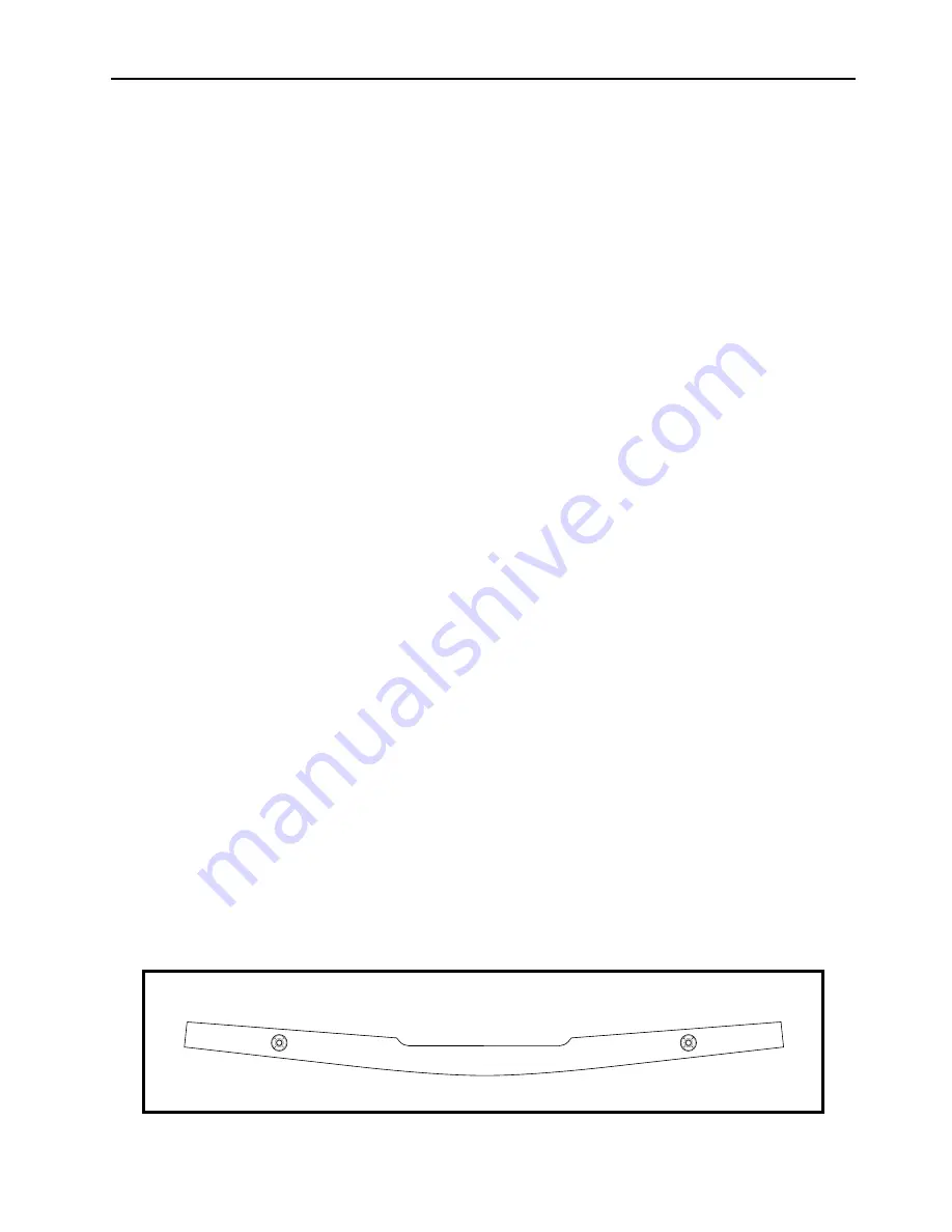
Figure 2
Summary of Contents for F.8L Falco
Page 1: ...F 8L Falco Construction Manual...
Page 7: ...l F 8L Falco Construction Manual Revision 4 March 1 2002...
Page 21: ...l F 8L Falco Construction Manual 1 8 Revision 4 March 1 2002...
Page 29: ...l F 8L Falco Construction Manual 2 8 Revision 4 March 1 2002...
Page 43: ...l F 8L Falco Construction Manual 5 4 Revision 4 March 1 2002...
Page 65: ...l F 8L Falco Construction Manual 9 6 Revision 4 March 1 2002...
Page 81: ...l F 8L Falco Construction Manual 10 16 Revision 4 March 1 2002...
Page 109: ...l F 8L Falco Construction Manual 15 4 Revision 4 March 1 2002...
Page 133: ...l F 8L Falco Construction Manual 17 10 Revision 4 March 1 2002...
Page 145: ...l F 8L Falco Construction Manual 18 12 Revision 4 March 1 2002...
Page 173: ...l F 8L Falco Construction Manual 21 10 Revision 4 March 1 2002...
Page 229: ...l F 8L Falco Construction Manual 23 40 Revision 4 March 1 2002...
Page 387: ...l F 8L Falco Construction Manual 28 26 Revision 4 March 1 2002...
Page 393: ...l F 8L Falco Construction Manual A 6 Revision 4 March 1 2002...


