l
F.8L Falco Construction Manual
24–7
Revision 4, March 1, 2002
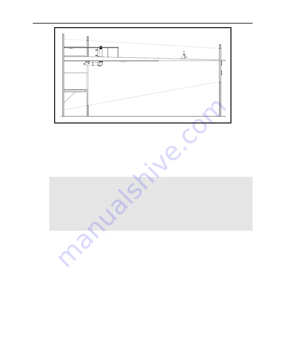
Figure 6
❏
Clamp the intermediate leading edge ribs (those ribs between the main wing spar and the
front wing spar) for wing Sta. 1, 2, 3 and 4 to the main wing spar as shown in Figure 6. Do
not sand the ends of the ribs at this time. Use a straightedge against the chord line drawn
on the rib at Sta. 4 to check the alignment of this rib. The chord line on the rib should
match the chord line drawn on the forward face of the spar and should be aligned with the
leading edge alignment string.
Note:
In the past, there has been some confusion about the exact location of the ribs at
Sta. 1. It is important that these ribs be installed on the centerline of the wing
station—the side load fittings (P/N 772-1 & 772-2) must be cleared, and when the landing
gear is retracted, the upper side load arm will nearly hit this rib as can been seen in
Drawing No. 102. Aft of the aft spar the rib is installed slightly outboard of the rest of the
Sta. 1 ribs.
In Figure 6 and all subsequent illustrations in this chapter, the supports of the centerboard
are not shown for frames No. 3, 4 and 5 so that you can see the details.
❏
Clamp the front wing spar to the intermediate leading edge ribs. Check for the correct
340mm dimension between the aft face of the main wing spar and the forward face of the
front spar (see Drawing No. 207). Use a water level to check that the front spar is
correctly installed. Trial fit the main landing gear leg to see that it will fit and that things
are correctly aligned (see Drawing No. 102).
❏
Sand the intermediate leading edge ribs as necessary so that they are in the proper position
and so that the front spar is in the correct position. These ribs may be sanded on both the
forward and aft ends.
❏
Glue the intermediate leading edge ribs to the main wing spar. It is a good idea to have
the front wing spar clamped in place and the landing gear leg in place.
❏
Glue the front wing spar to the intermediate leading edge ribs. The landing gear leg must
be in place during this operation.
Summary of Contents for F.8L Falco
Page 1: ...F 8L Falco Construction Manual...
Page 7: ...l F 8L Falco Construction Manual Revision 4 March 1 2002...
Page 21: ...l F 8L Falco Construction Manual 1 8 Revision 4 March 1 2002...
Page 29: ...l F 8L Falco Construction Manual 2 8 Revision 4 March 1 2002...
Page 43: ...l F 8L Falco Construction Manual 5 4 Revision 4 March 1 2002...
Page 65: ...l F 8L Falco Construction Manual 9 6 Revision 4 March 1 2002...
Page 81: ...l F 8L Falco Construction Manual 10 16 Revision 4 March 1 2002...
Page 109: ...l F 8L Falco Construction Manual 15 4 Revision 4 March 1 2002...
Page 133: ...l F 8L Falco Construction Manual 17 10 Revision 4 March 1 2002...
Page 145: ...l F 8L Falco Construction Manual 18 12 Revision 4 March 1 2002...
Page 173: ...l F 8L Falco Construction Manual 21 10 Revision 4 March 1 2002...
Page 229: ...l F 8L Falco Construction Manual 23 40 Revision 4 March 1 2002...
Page 387: ...l F 8L Falco Construction Manual 28 26 Revision 4 March 1 2002...
Page 393: ...l F 8L Falco Construction Manual A 6 Revision 4 March 1 2002...


