l
F.8L Falco Construction Manual
24–24
Revision 4, March 1, 2002
❏
Drill one rivet hole for P/N 714 with a #30 (.128ӯ) drill. See Drawing No. 781. Remove
the aileron pushrod from the airplane and drill the second rivet hole for P/N 714. Install
the rivets for P/N 714.
Note:
The normal practice when installing 5/32” rivets is to first drill with a 5/32”Ø drill
and then ream with a #21 (.159ӯ) drill before installing the rivet. We suggest that you
drill the first hole with a #30 (.128”Ø) or a 1/8”Ø drill, then ream up to 5/32” and #21.
Drilling the first hole smaller will be a safer way to proceed.
After drilling a hole for a rivet, the normal practice is to use a Cleco to hold the parts in
position. If you do not have Clecos you may use drills for the same purpose. If the first
rivet hole is a #30, then insert a #30 drill in the hole while you drill the second hole with a
1/8ӯ drill. Leave one of the drills in place while you ream the other hole up to 5/32ӯ
and finally with a #21 drill. Deburr the hole by lightly twisting a larger drill in the holes
and insert the rivet. If you do not have a rivet gun, you may set the rivet with a hammer,
although it is best to use a rivet set on the opposite end of the rivet. When this rivet is set,
you may ream up the other hole and set that rivet.
❏
Put the aileron pushrod back in the airplane and check the length of the pushrod. Make
any final adjustments necessary in the length of the pushrod and then drill for one of the
rivets for P/N 712—see Drawing No. 781.
❏
Remove the pushrod from the airplane and install the rivets for P/N 712.
❏
Install the aileron pushrod in the wing.
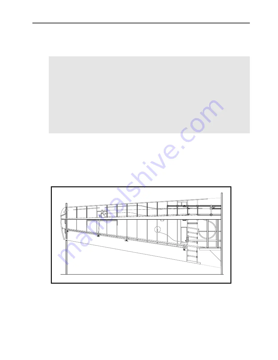
Figure 34
❏
In the left wing, install the plastic tubing as conduit for the wires for the navigation and
strobe light and for the heated pitot. The position of the couduit is shown on the rib
drawings. The tubing has a break between Sta. 10 and 11 as shown on Drawing No. 201
Sheet 1. The reason for this break in the conduit is that the wiring for the heated pitot
must be routed to the pitot tube. Note that the 1/4” O.D. pitot line will also be routed
with the conduit in the left wing.
Summary of Contents for F.8L Falco
Page 1: ...F 8L Falco Construction Manual...
Page 7: ...l F 8L Falco Construction Manual Revision 4 March 1 2002...
Page 21: ...l F 8L Falco Construction Manual 1 8 Revision 4 March 1 2002...
Page 29: ...l F 8L Falco Construction Manual 2 8 Revision 4 March 1 2002...
Page 43: ...l F 8L Falco Construction Manual 5 4 Revision 4 March 1 2002...
Page 65: ...l F 8L Falco Construction Manual 9 6 Revision 4 March 1 2002...
Page 81: ...l F 8L Falco Construction Manual 10 16 Revision 4 March 1 2002...
Page 109: ...l F 8L Falco Construction Manual 15 4 Revision 4 March 1 2002...
Page 133: ...l F 8L Falco Construction Manual 17 10 Revision 4 March 1 2002...
Page 145: ...l F 8L Falco Construction Manual 18 12 Revision 4 March 1 2002...
Page 173: ...l F 8L Falco Construction Manual 21 10 Revision 4 March 1 2002...
Page 229: ...l F 8L Falco Construction Manual 23 40 Revision 4 March 1 2002...
Page 387: ...l F 8L Falco Construction Manual 28 26 Revision 4 March 1 2002...
Page 393: ...l F 8L Falco Construction Manual A 6 Revision 4 March 1 2002...


