l
F.8L Falco Construction Manual
25–7
Revision 4, March 1, 2002
115
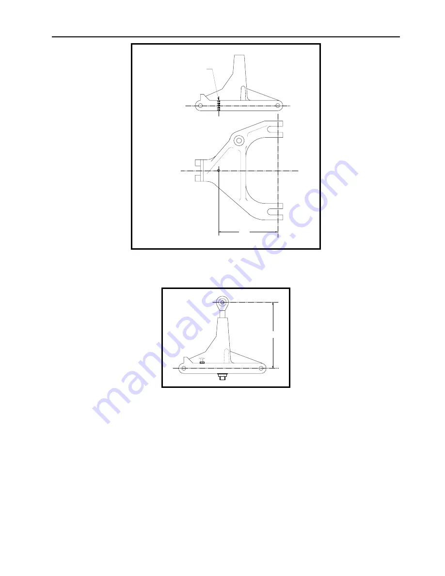
drill #21 (.1590"Ø)
tap 10-32
Figure 3
❏
Drill and tap the hole in P/N 618A for the gear up limit switch screw. See Figure 3.
128
Figure 4
❏
Install P/N 605 in P/N 618A. See Drawing No. 105. The approximate installed location
of P/N 605 is shown in Figure 4.
❏
Install the MS35207-267 screw and AN315-3 check nut (included in the Electrical kit) in
P/N 618A upper drag strut. See Figure 4.
❏
Install P/N 708 drag strut supports in P/N 618A upper drag strut. See Drawing No. 105
and 114. If the bolts are too tight in P/N 708, ream the holes with a 5/16” reamer or drill.
❏
Install P/N 619A on P/N 618A. See Drawing No. 105.
❏
Install P/N 619A (with the other parts installed) on the nose gear. See Drawing No. 105.
Summary of Contents for F.8L Falco
Page 1: ...F 8L Falco Construction Manual...
Page 7: ...l F 8L Falco Construction Manual Revision 4 March 1 2002...
Page 21: ...l F 8L Falco Construction Manual 1 8 Revision 4 March 1 2002...
Page 29: ...l F 8L Falco Construction Manual 2 8 Revision 4 March 1 2002...
Page 43: ...l F 8L Falco Construction Manual 5 4 Revision 4 March 1 2002...
Page 65: ...l F 8L Falco Construction Manual 9 6 Revision 4 March 1 2002...
Page 81: ...l F 8L Falco Construction Manual 10 16 Revision 4 March 1 2002...
Page 109: ...l F 8L Falco Construction Manual 15 4 Revision 4 March 1 2002...
Page 133: ...l F 8L Falco Construction Manual 17 10 Revision 4 March 1 2002...
Page 145: ...l F 8L Falco Construction Manual 18 12 Revision 4 March 1 2002...
Page 173: ...l F 8L Falco Construction Manual 21 10 Revision 4 March 1 2002...
Page 229: ...l F 8L Falco Construction Manual 23 40 Revision 4 March 1 2002...
Page 387: ...l F 8L Falco Construction Manual 28 26 Revision 4 March 1 2002...
Page 393: ...l F 8L Falco Construction Manual A 6 Revision 4 March 1 2002...


