background image

Diaphragm Relief Valve 


Operating Instructions 


TA  48 

Rev. 

13  en 

05/2016 

Subject to technical modifications! 

www.sera-web.com 

17 


17 

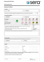
Clearance Certificate 


NOTE! 


Inspection / repair of machines and machine parts is only 
carried out after the opposite clearance certificate was 
filled in correctly and completely by authorized and quali-
fied personnel. 


NOTE! 


Acceptance will be refused if parts are returned to the 
manufacturer without a proper clearance certificate


All  industrial  companies  are  obligated  by  the  legal  provisions 
for  occupational  health,  e.g.  the  workplaces  ordinances,  the 
Ordinance  on  Hazardous Substances,  the  regulations for  pre-
vention  of  accidents  and  the  environmental  protection  regula-
tions  such  as  the  Waste  Management  Act  and  the  German 
Household  Water  Act  to  protect  their  employees  or  man  and 
the  environment  from  detrimental  effects  when  handling  haz-
ardous substances. 
 
Should special safety precautions be necessary despite careful 
draining and cleaning of the product the necessary information 
are to be provided. 
 
Machines which are operated with radioactive media shall only 
be 

inspected 

and/or 

repaired 

in 

the 

safety 

area of the owner by a 

sera

 specialized fitter. 

 
The clearance certificate is part of the inspection-/repair order. 

sera

  reserves  the  right  to  refuse  acceptance  of  the  order  for 

other reasons. 


NOTE! 


Please make a copy and leave the original with the operat-
ing instructions! 

(can also be downloaded from: www.sera-web.com)


Summary of Contents for 620.10

Page 1: ...ct type and serial number of your diaphragm relief valve can be read off the type plate on the diaphragm relief valve Type Serial No These data are important in case of queries or for ordering spare a...

Page 2: ...ction for maintenance and service 5 4 Areas of application and function 6 5 Test identification 6 6 Checking the packaging at the place of destination 6 7 Storage 6 8 Technical specifications 7 8 1 Di...

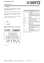
Page 3: ...factory provided with a type plate The following information can be found on this type plate 1 2 3 4 5 6 Fig 01 Type plate Explanation of the indications on the type plate 1 Pe Set pressure The set pr...

Page 4: ...corresponding accident pre vention measures to protect operating personnel from danger through the pumped media used 3 2 Marking of notes 3 2 1 Marking of notes in these operating instructions Special...

Page 5: ...on Temperature of the pumped medium sera does not assume any responsibility if these criteria are not or only partly observed by the owner operator CAUTION The structural design of the diaphragm relie...

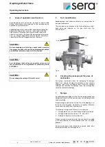
Page 6: ...valves are tested in our works and set to an operative pressure The set pressure corresponds to the technical delivery condi tions which are indicated on the type plate see Fig 01 02 Table 01 Lid Seal...

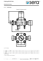
Page 7: ...Fig 03 Dimensions Type DN G A B H L1 n g 1 i 1 p 1 L2 D k s d PP PVC 620 10 8 G 50 38 80 80 13 M5 15 5 110 90 60 12 10 14 622 10 15 G 1 72 54 90 115 15 M8 17 8 145 95 65 12 11 14 623 10 20 G 1 80 60 1...

Page 8: ...ns TA 48 Rev 13 en 05 2016 L g DN n H p i G q B q A 8 1 2 1 4581 design Connection Thread pipe connection Fig 04 Dimensions Type DN G A B H L n g 1 i 1 p 1 620 10 8 G 50 38 80 110 13 M5 10 5 622 10 15...

Page 9: ...g to DIN 2501 PN 10 ANSI 150 lbs sq in Fig 05 Dimensions Type DN A B H L D 1 D 2 k 1 k 2 l 1 l 2 623 10 20 80 60 125 150 105 99 75 70 14 16 624 10 25 90 68 130 160 115 108 85 79 14 16 625 10 32 100 76...

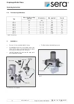
Page 10: ...626 10 10 1 5 10 7000 6 7 627 10 10 1 5 10 10000 9 12 Table 05 Technical data 9 Installation The cover is to be mounted vertically to the top The diaphragm relief valve is to be installed in such a wa...

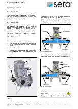
Page 11: ...d 10 Start up During commissioning observe the following Open all shut off valves that are mounted in the suction line and pressure line except for flushing and discharge fittings Start pump system Sl...

Page 12: ...aphragm relief valves are factory set to the set pressure stated in the order confirmation A sealing wax seal is located on the transition piece between lid and cover 12 Operation in explosion hazardo...

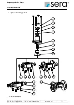
Page 13: ...perating Instructions TA 48 Rev 13 en 05 2016 Subject to technical modifications www sera web com 13 13 1 Spare and wearing parts kit Fig 12 Spare and wearing parts kit 2 3 4 5 9 7 8 10 11 12 13 14 15...

Page 14: ...flange Item Designation 1 Hexagon screws 2 Disks 3 Lid 4 O ring 6 Cover 15 O rings 16 Valve body 17 Disks 18 Nuts Valve body kit 1 4581 Item Designation 1 Hexagon screws 2 Disks 3 Lid 4 O ring 6 Cover...

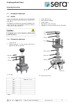
Page 15: ...e EC safety data sheets CAUTION The diaphragm may only be replaced by authorized and qualified personnel 14 2 Changing the diaphragm Unscrew the lid Measure dimension T of the set screw with a caliper...

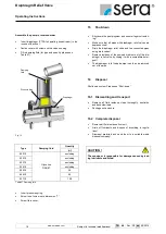
Page 16: ...n Shut down the pump system and secure it against restart ing Make sure that all pipes with diaphragm relief valves are depressurized Drain the diaphragm relief valve and the connected pipes using dra...

Page 17: ...ns for pre vention of accidents and the environmental protection regula tions such as the Waste Management Act and the German Household Water Act to protect their employees or man and the environment...

Page 18: ...Diaphragm Relief Valve Operating Instructions 18 www sera web com Subject to technical modifications TA 48 Rev 13 en 05 2016...

Page 19: ...Diaphragm Relief Valve Operating Instructions TA 48 Rev 13 en 05 2016 Subject to technical modifications www sera web com 19 Notes...

Page 20: ...Diaphragm Relief Valve Operating Instructions 20 www sera web com Subject to technical modifications TA 48 Rev 13 en 05 2016...

Reviews: