Systèmes de dosage – construction verticale
CVD 1 (s) / CVD 2
Notice d’utilisation
TA450-11 / fr/en / 01.2017 / PM
www.sera-web.com
Sous réserve de modifications techniques !
Subject to technical modifications!
41
7.1.10 CVD1 - Option
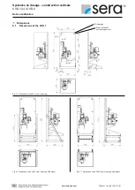
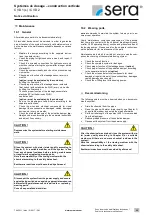
stand for floor mounting
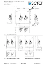
The system is installed on a mounting plate for wall mounting
as standard. A stand for floor mounting is available as option if
there are no possibilities for wall mounting at the installation
site.
Fig.18 Option stand for floor mounting
7.2
CVD2
7.2.1 CVD2 – Basic unit
The chemical is dosed by two diaphragm pumps. The convey-
ing capacities of the pump can be adjusted at the manual
stroke length adjustment. Depending on the design of the dos-
ing pump, an additional automatic dosing is possible via pulse
or analogue signals.
The piping on the pressure side consists of a taper seat non-
return valve and a ball valve as end connection. The pumps
are protected against overpressure by an overflow valve. A
drain ball valve for evacuation/pressure relief is fitted in the
pressure pipe.
The pipes on the pressure and the suction side of the basic
unit are not connected with each other.
The pumps and the corresponding fittings are mounted on a
wall mounting plate with collecting basin.
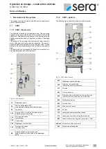
Fig. 19 CVD2 basic unit
10
2 pcs. diaphragm pumps
20
Wall mounting plate of PP
(with integrated collecting basin and drain plug)
40
Type plate
100
Piping of PVC-U or PP on the pressure side
End connection male thread
110
2 pcs. two-way ball valves
(shut-off valves)
120
2 pcs. check valves
130
2 pcs. diaphragm overflow valves
140
2 pcs. two-way ball valves
(discharge valves)
N2
End connection on the suction side:
Male thread for suction valve of the diaphragm
pumps
without
Protective roof for drive motor
500
Detachable splash guard

