Systèmes de dosage – construction verticale
CVD 1 (s) / CVD 2
Notice d’utilisation
TA450-11 / fr/en / 01.2017 / PM
www.sera-web.com
Sous réserve de modifications techniques !
Subject to technical modifications!
47
Installation and assembly
The following points must be observed when the dosing sys-
tem is installed:
•
Check the complete dosing system for damage (e.g.
transport damage).
•
The system is designed for indoor installation and must
be protected from direct sunlight.
•
Build in the dosing system and attach it with appropriate
material.
•
The pipings on the suction and pressure side must be
sufficiently dimensioned.
•
Connect all pipes and make sure that they are tension-
and vibration-free. An offset of the pipes within the area
of the screwed and flanged connections must be avoided
by all means.
•
Connect the return pipe from the overflow valve so that a
free and unhindered backflow of the medium is guaran-
teed (directly into the corresponding tank or using the op-
tion according to Chapter 7.1.5).
•
Replace the transport closure (oil sight glass with seal) at
the oil filler cap of the pump with the attached vent screw
(observe the notes on the pump!)
.
•
The electrical connections are to be made in accordance
with the VDE (Association of German Electrotechnical
Engineers) or the local electrical regulations applicable.
Please see Chapter 8.4
“Electrical connection”
.
8.1
Place of installation
•
The place of installation must be frost resisting and ven-
tilated.
•
An installation in an aggressive or explosion-hazardous
area is not permitted.
•
The installation data according to the Appendix must be
regarded.
•
The installation site must be equipped with proper light-
ing for all works to be carried out (installation, operation,
maintenance etc.).
•
Leaking chemicals must be disposed off in a safe and
secure manner at the installation site.
CAUTION !
Pay attention to the safety data sheet of the pumped me-
dium! The instructions in the safety data sheet regarding
handling of the medium must be observed!
8.2
Wall mounting
Attach the system to the wall at a suitable height. Select the
installation height so that operation and maintenance of the
system are possible at any time.
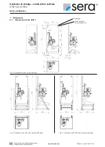
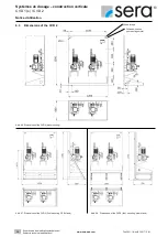
The position of the bore holes is shown in figure 03 for the
CVD1 and figure 06 for the CVD2 in Chapters 6.1 and 6.2
“Dimensions”.
CAUTION !
The fastening material is not included in the scope of
supply and must be provided by the customer depending
on the condition of the wall!
CAUTION !
Pay attention to the carrying capacity of the wall.
The wall must be flat so that the wall mounting plate can
be fixed without tension.
8.3
Floor mounting
Fasten the stand to the floor. Place the system in such a way
that operation and maintenance are possible at any time.
See in figures 04/05 for the CVD1 and figures 07/08 for the
CVD2 in Chapters 6.1 and 6.2 “Dimensions”.
CAUTION !
The fastening material is not included in the scope of
supply and must be provided by the customer depending
on the condition of the floor!
CAUTION !
The mounting area must be flat.
Take appropriate measures in order to compensate for
height differences so that the stand can be fastened with-
out tension.

