background image


2

3

Thanks for choosing Seraphim Photovoltaic Modules (hereafter referred to as 

“PV Module”), This Guide is to give information on how to apply Seraphim PV 

modules properly. 

Installers must read and understand this Guide prior to installation. For any 
questions, please contact our technical department (technic@seraphim-ener-
gy.com) for further information. Installers should follow all safety precautions 
described in this Guide as well as local codes when installing a module. 

Keep this Guide in a safe place for future reference (care and maintenance) and 
in case of sale or disposal of the PV modules.  

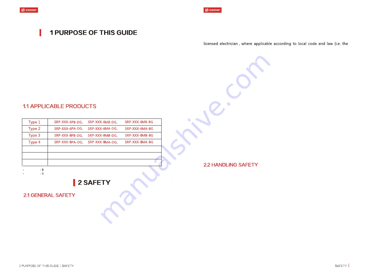
This document is applicable to the series of PV modules as listed below:

 The PV modules are qualified for application class A, which may be used in 

systems operating at greater than 50 V DC or 240 W, where general contact 
access is anticipated. PV modules qualified for safety through this part of IEC 
61730 and IEC 61730-2 and within this application class are considered to meet 
the requirements for safety class II. 

 The PV modules shall be properly grounded in accordance with the instruc-

tions in this Guide or the requirements of the National Electrical Code. 

  Installing  PV  modules  requires  specialized  skills  and  knowledge.  Installation 

should only be performed by qualified personnel, electrical connections requires a 

NEC for the USA and CEC for Canada). 

 Installers should assume all risks of injury that might occur during installation, 

including, but not limited to, the risk of electric shock. 

 One single PV module may generate more than 30V DC when exposed to direct 

sunlight. Access to a DC voltage of 30V or more is potentially hazardous. 

• PV modules con

vert light energy to DC electrical energy, which are designed for 

outdoor use. PV modules can be mounted onto ground, rooftop, vehicles or boats 
etc. The proper design of support structures lies within responsibility of the system 
designers and installers.   

  Do  not  use  mirrors  or  other  magnifiers  to  concentrate  sunlight  onto  the  PV 

modules.  

 When installing the PV modules, abide to all local, regional and national statuto-

ry regulations. Obtain a building permit if necessary.

 Only use equipment, connectors, wiring and support frames compatible with the 

PV modules.  

• Do not li

ft the PV module by grasping the module’s junction box or electrical 

leads. 

• Do not stand or s

tep on the PV modules or place heavy objects onto it.

• Do not d

rop the PV module or allow objects to fall on the PV module. 

• Do handle with ca

re when move, transport and install the PV modules.

• Do not lean modules on other objects.

 Do apply soft protector to separate the modules when stacking modules and 

ensure the safety

• Do 

not attempt to disassemble the PV modules, and do not remove any 

attached nameplates or components from the PV modules. 

INSTALLATION GUIDE FOR SERAPHIM 

DUAL GLASS PHOTOVOLTAIC MODULE

INSTALLATION GUIDE FOR SERAPHIM 

DUAL GLASS PHOTOVOLTAIC MODULE

DG Module

ingle side dual-glass module

BG Module

ifacial dual-glass module

XXX

Module power

:_VK

5

986>>>(3

Z

(-

986>>>(3

C

(-

:_VK

6

986>>>(3

D

(-

:_VK

7

Summary of Contents for SRP 6MA-DG

Page 1: ... DG AND BG PHOTOVOLTAIC MODULE JIANGSU SERAPHIM PHOTOVOLTAIC SYSTEM CO LTD ADDRESS No 10 TongshunRD Henglin Town Wujin District Changzhou China TELEPHONE 86 519 69699879 MAILBOX info seraphim energy com 2 1V1 0 ...

Page 2: ...might occur during installation including but not limited to the risk of electric shock One single PV module may generate more than 30V DC when exposed to direct sunlight Access to a DC voltage of 30V or more is potentially hazardous PV modules convert light energy to DC electrical energy which are designed for outdoor use PV modules can be mounted onto ground rooftop vehicles or boats etc The pro...

Page 3: ... including wires and cables connectors charging regulators inverters storage batteries recharge able batteries etc Under normal outdoor conditions the current and voltage generated will differ from those listed on the datasheet When design systems current and short circuit current should be multiplied by a factor of 1 25 to determine components ratings Only use connectors compatible with the PV mo...

Page 4: ...ellent sunlight resources In the Northern Hemisphere the module should typically face south and in the Southern Hemisphere the modules should typically face north The most optimistic installation angle varies according to different latitudes and longitudes please con sult experts with appropriate knowledge background when determining the instal lation locations and angles When choosing a site avoi...

Page 5: ...rd force of up to 5400 Pa 550 kg m2 the modules shall be fixed on the bracket with the long side of the module using a minimum of four clamps Please make sure to use at least of two purlins behind the modules to support the modules The selection and installation of the clamps shall obey the requirement accord ing to table 3 Otherwise the module may not satisfy the mechanical load and have the risk...

Page 6: ...1 5400 2400 Type 5 S E R IAL NUMB E R S E R IAL NUMB E R 1 8L 1 4L 1 8L 1 4L L 5 5 _VK 6 _VK 7 SS 5 SS INSTALLATION GUIDE FOR SERAPHIM DUAL GLASS PHOTOVOLTAIC MODULE The dual glass module with frame is also designed for screw installation It needs the screws bolts nuts and washers to fix on the bracket as shown in fig7 Sufficient torque should be applied to the bolts to ensure stable reinforcement...

Page 7: ...E 45 5 0 53 45 5 0 12 13 Loads Pa Screw Number Installation Drawing Installation Site Outer four holes Inner four holes 4 2400 2400 2400 2400 4 Table 4 Outer four holes Inner four holes 5400 2400 2400 2400 8 4 Nextracker holes Loads Pa Screw Number Installation Drawing Installation Site 6 53 45 5 0 WARNING Electrical Hazard This module produces electricity when exposed to light Follow all appli ca...

Page 8: ...ctor is 105 C A qualified system designer or integrator should always be consulted Building permits inspections and approvals by the local utility are generally required 14 45 5 0 53 45 5 0 15 If the connector is damaged or deformed Before installation make sure that the connector is well protected and there should be no foreign matter such as soil sand and gravel in the connector If any it must b...

Page 9: ...uires series DC input bus terminal must be MC4 Inspection before use 1 Confirm the original MC4 connector of the conversion cable and compatible MC4 connector 2 Make sure that the connector on the conversion cable is not detached or loose and the metal core is not skewed or water stained etc 3 Confirm that the cable insulation layer of the conversion cable is not damaged and the cable is not severel...

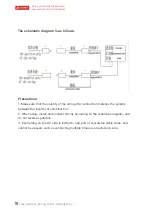
Page 10: ...n matches the polarity between the inverter or combiner box 2 When using install and connect strictly according to the schematic diagram and do not reverse operation 3 Each string on the DC side is limited to one pair of conversion cable wires and cannot be abused such as connecting multiple times as an extension wire The schematic diagram is as follows ...

Reviews: