background image

$-".1*/45"--"5*0/

6

.&$)"/*$"-*/45"--"5*0/

.&$)"/*$"-*/45"--"5*0/

7

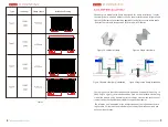
The frameless dual glass module is designed for clamp installation. It need the 

clamps with rubber strips to fix on the bracket. Figure 1 and figure 2 show the structure 

of two kind of clamps.

Figure 1 Double-side clamp

Table 1 Components of the clamp

NO.

Name

Remark

Aluminium alloy

6063-T5

Spring

Bolt

M8 stainless steel bolt

Rubber strip

Ethylene Propylene 

*OKTK36*3ͨ

1

2

3

4

Figure 2 Single-side clamp

INSTALLATION GUIDE FOR SERAPHIM 

DUAL GLASS PHOTOVOLTAIC MODULE

INSTALLATION GUIDE FOR SERAPHIM 

DUAL GLASS PHOTOVOLTAIC MODULE

-0$"5*0/"/%"/(-&4&-&$5*0/

(&/&3"-*/45"--"5*0/13*/$*1-&

• Module can be installed in both landscape and portrait modes

1

• The clamp shall not shade the front side of the cells.

• The PV modules shall be installed high enough to keep it away from potential 
shading, flying sands, snow and water.

• It is recommended to install the PV modules 30cm away from the ground to make 

sure ventilation. 

• Appropriate installation structures shall be chosen to meet required mechanical 
load. 

• It is recommended to install the PV modules with minimum angle of 10 degree to 
make the dust easily to be washed off. 

• It is recommended to keep minimum 2cm gap between PV modules for thermal 

expansion of materials.

• Install PV modules appropriately according to corresponding mechanical load 
need.

It is recommended to install PV modules where has excellent sunlight resources. In 

the Northern Hemisphere, the module should typically face south, and in the 

Southern Hemisphere, the modules should typically face north. The most optimistic 
installation angle varies according to different latitudes and longitudes; please con

-

sult experts with appropriate knowledge background when determining the instal

-

lation locations and angles.

When choosing a site, avoid trees, buildings or obstructions, which could cast 

shadows on the solar photovoltaic modules. Shading causes hotspot and loss of 
output, even though the factory fitted bypass diodes of the PV module will mini

-

mize such effect. 

Do not install the PV module near naked flame or flammable materials. 

Do not install the PV module in a location where it would be immersed in water or 

constantly exposed to water from a sprinkler or fountain etc. 

• It is recommended to install the bifacial modules 1m away from the ground or roof 
to maintain the energy yield of module rear side.

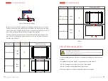
In order to ensure that the modules can withstand a downward force of up to 

2400 Pa (244 kg/m2), the modules shall be fixed on the bracket with the long 

side of the module, using a minimum of four clamps. Please make sure to use at 
least of two purlins behind the modules to support the modules.

The selection and installation of the clamps shall obey the requirement accord

-

ing to table 2. Otherwise the module may not satisfy the mechanical load and 

-

have the risk of broken.

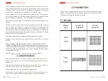
The applied torque should be big enough to fix it steadily.The reference torque 
for screw  

1

4

2

2

1

4

is 16~20N*m. 

Summary of Contents for SRP 6MA-DG

Page 1: ... DG AND BG PHOTOVOLTAIC MODULE JIANGSU SERAPHIM PHOTOVOLTAIC SYSTEM CO LTD ADDRESS No 10 TongshunRD Henglin Town Wujin District Changzhou China TELEPHONE 86 519 69699879 MAILBOX info seraphim energy com 2 1V1 0 ...

Page 2: ...might occur during installation including but not limited to the risk of electric shock One single PV module may generate more than 30V DC when exposed to direct sunlight Access to a DC voltage of 30V or more is potentially hazardous PV modules convert light energy to DC electrical energy which are designed for outdoor use PV modules can be mounted onto ground rooftop vehicles or boats etc The pro...

Page 3: ... including wires and cables connectors charging regulators inverters storage batteries recharge able batteries etc Under normal outdoor conditions the current and voltage generated will differ from those listed on the datasheet When design systems current and short circuit current should be multiplied by a factor of 1 25 to determine components ratings Only use connectors compatible with the PV mo...

Page 4: ...ellent sunlight resources In the Northern Hemisphere the module should typically face south and in the Southern Hemisphere the modules should typically face north The most optimistic installation angle varies according to different latitudes and longitudes please con sult experts with appropriate knowledge background when determining the instal lation locations and angles When choosing a site avoi...

Page 5: ...rd force of up to 5400 Pa 550 kg m2 the modules shall be fixed on the bracket with the long side of the module using a minimum of four clamps Please make sure to use at least of two purlins behind the modules to support the modules The selection and installation of the clamps shall obey the requirement accord ing to table 3 Otherwise the module may not satisfy the mechanical load and have the risk...

Page 6: ...1 5400 2400 Type 5 S E R IAL NUMB E R S E R IAL NUMB E R 1 8L 1 4L 1 8L 1 4L L 5 5 _VK 6 _VK 7 SS 5 SS INSTALLATION GUIDE FOR SERAPHIM DUAL GLASS PHOTOVOLTAIC MODULE The dual glass module with frame is also designed for screw installation It needs the screws bolts nuts and washers to fix on the bracket as shown in fig7 Sufficient torque should be applied to the bolts to ensure stable reinforcement...

Page 7: ...E 45 5 0 53 45 5 0 12 13 Loads Pa Screw Number Installation Drawing Installation Site Outer four holes Inner four holes 4 2400 2400 2400 2400 4 Table 4 Outer four holes Inner four holes 5400 2400 2400 2400 8 4 Nextracker holes Loads Pa Screw Number Installation Drawing Installation Site 6 53 45 5 0 WARNING Electrical Hazard This module produces electricity when exposed to light Follow all appli ca...

Page 8: ...ctor is 105 C A qualified system designer or integrator should always be consulted Building permits inspections and approvals by the local utility are generally required 14 45 5 0 53 45 5 0 15 If the connector is damaged or deformed Before installation make sure that the connector is well protected and there should be no foreign matter such as soil sand and gravel in the connector If any it must b...

Page 9: ...uires series DC input bus terminal must be MC4 Inspection before use 1 Confirm the original MC4 connector of the conversion cable and compatible MC4 connector 2 Make sure that the connector on the conversion cable is not detached or loose and the metal core is not skewed or water stained etc 3 Confirm that the cable insulation layer of the conversion cable is not damaged and the cable is not severel...

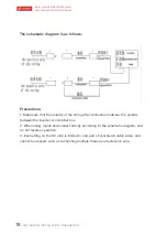
Page 10: ...n matches the polarity between the inverter or combiner box 2 When using install and connect strictly according to the schematic diagram and do not reverse operation 3 Each string on the DC side is limited to one pair of conversion cable wires and cannot be abused such as connecting multiple times as an extension wire The schematic diagram is as follows ...

Reviews: