background image

Using the Windows Utility 

13 

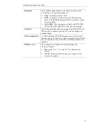
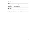
Network Type 

Select the desired option:  


Infrastructure

 - Select this to connect to an Access point.  


Ad-Hoc

 - Select this if you are connecting directly to another 

computer. 

Tx Power 

Select the Tx (transmission) power according to the real envi-
ronment. 

Preamble 

The preamble defines the length of the CRC (cyclic redundancy 
check). Select either 

Auto

 or 

Long Preamble

OK button 

Click this button to save the settings and close the page. 

Cancel button 

The "Cancel" button will discard any data you have entered and 
exit the page. 

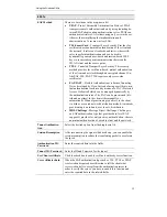
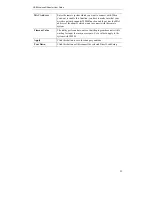
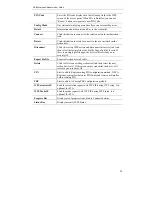
Auth./Encyp. 

Authentication 

You MUST select the option to match the Wireless LAN you 
wish to join. The available options are: 


Open 

- Broadcast signals are not encrypted. This method can 

be used only with no encryption or with WEP. 


Shared 

- Broadcast signals are encrypted using WEP. This 

method can only be used with WEP. 


LEAP

 - Light Extensible Authentication Protocol is a pre-

EAP, Cisco-proprietary protocol. If selected, you have to en-
ter the identity, password and domain name of your 
computer. 


WPA

 - This version of WPA requires a Radius Server on 

your LAN to provide the client authentication according to 
the 802.1x standard. Data transmissions are encrypted using 
the WPA standard. 


WPA-PSK

 - PSK means "Pre-shared Key". You must enter 

this Passphrase value; it is used for both authentication and 
encryption.  


WPA2

 - This version of WPA2 requires a Radius Server on 

your LAN to provide the client authentication according to 
the 802.1x standard. Data transmissions are encrypted using 
the WPA2 standard. 


WPA2-PSK

 - This is a further development of WPA-PSK, 

and offers even greater security. You must enter this Pass-
phrase value; it is used for both authentication and 
encryption.  


WPA None

 - If selected, you can only set encryption and 

WPA-Preshared Key settings. 


Summary of Contents for UB801R v3

Page 1: ...UB801R v3 USB Wireless G Adapter ...

Page 2: ...ii User Guide ...

Page 3: ...n 11 Profile Screen 12 Advanced Screen 17 Statistics Screen 19 WMM Screen 21 WPS Screen 23 Radio on off Screen 25 About Screen 26 APPENDIX A SPECIFICATIONS 27 Wireless USB Dongle 27 APPENDIX B ABOUT WIRELESS LANS 28 Modes 28 BSS ESS 28 Channels 29 WEP WPA PSK 29 WPA2 PSK 29 Wireless LAN Configuration 30 P N 956YMJ0030 Copyright 2008 All Rights Reserved Document Version 1 0 2008 All trademarks and ...

Page 4: ......

Page 5: ... transmission rate is up to 54Mbps Supports Turbo Mode which can enhance the data transmission rate within the specific wireless network Supports WMM Wi Fi Multimedia function IEEE 802 11e QoS standard and can meet the requirement of the multi media data bandwidth Supports 64 128 bit WEP WPA TKIP with IEEE802 1x and WPA2 AES with IEEE 802 1x functions for high level security Supports CCS Cisco Com...

Page 6: ...less G Adapter User Guide 2 Operation You should install the supplied software on the CD ROM before inserting the Wireless USB Dongle If you have any form of the wireless utility beforehand please uninstall it ...

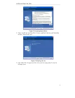
Page 7: ...and IEEE802 11g wireless LAN Procedure You should install the supplied software BEFORE inserting the Wireless USB Dongle 1 Insert the CD ROM into the drive on your PC 2 The installation program should start automatically If it does not run the Setup exe program Figure 1 Start Installation 3 On the License Agreement screen select I accept the terms of the license agreement Click Next 2 ...

Page 8: ... Screen 4 Choose Install driver and Allnet WLAN Utility to install both the driver and Allnet utility software or Install driver only Figure 3 Setup Type Screen 5 Select either Allnet Configuration Tool or Microsoft Zero configuration Tool on the following screen ...

Page 9: ...following screen click Install 7 Click Finish to exit the Wizard 8 Insert the Wireless USB Dongle firmly into USB port of the PC 9 If the Wireless USB Dongle was installed properly you will now have a new icon in your system tray as shown below Figure 5 System Tray Icon ...

Page 10: ... the Wireless USB Dongle is established The length of green color indicates the signal strength No connection to the Wireless USB Dongle The Wireless USB Dongle is unplugged 10 You can double click this icon to configure the Wireless interface See the following chapter for details ...

Page 11: ...ed Wireless utility System Tray Icon If the Wireless Utility program is running you can double click the icon in the System Tray or right click the icon and select Launch Config Utility to open the application Status Information The menu options available from the System Tray icon are Launch Config Utility This will display the main screen of the Utility Use Zero Configuration as configuration Uti...

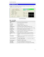
Page 12: ...an all the channels to find all the access points stations within the accessible range and automatically connect to one of the wireless devices which have the highest signal strength Figure 7 Network Screen Data Network Screen SSID The SSID up to 32 printable ASCII characters is a unique name identified in a WLAN Network Type It displays the Network type in use Infrastructure for BSS Ad Hoc for IB...

Page 13: ...to a new profile Connect Click this button to connect the Wireless network Wireless Network Sequence order You can click the radio buttons in the Sort by section ex SSID Channel or Signal to arrange the Wireless network in the desired order To Connect to a Wireless Network Click the name of the wireless network to which you want to connect and then click Connect Note that once you are connected to...

Page 14: ...s infrastructure mode It indicates network type is Ad hoc mode 802 11b wireless mode 802 11g wireless mode 802 11n wireless mode It indicates security enabled wireless network It shows the information of Link Status Section It hides the information of Link Status Section ...

Page 15: ... Network Type This will indicate Infrastructure or Ad hoc IP Address It shows the current IP address on the wireless interface Subnet Mask Subnet mask for the current IP address Default Gateway Gateway IP address associated with the current IP address HT It displays current HT status in use 802 11n wireless card only Link Quality It displays connection quality based on signal strength and TX RX pa...

Page 16: ...ctions below Figure 10 Profile Screen Data Profile Screen System Config Profile Name Enter or select a suitable name for this profile Each profile must have a unique name SSID If the desired wireless network is currently available you can select its SSID Otherwise type in the SSID of the desired wire less network Power Save Mode Select either CAM Constantly Awake Mode or PSM Power Saving Mode RTS ...

Page 17: ...nals are encrypted using WEP This method can only be used with WEP LEAP Light Extensible Authentication Protocol is a pre EAP Cisco proprietary protocol If selected you have to en ter the identity password and domain name of your computer WPA This version of WPA requires a Radius Server on your LAN to provide the client authentication according to the 802 1x standard Data transmissions are encrypt...

Page 18: ... the correct option Use 802 1x This setting only takes effect when using Open Shared WPA or WPA2 mode If enabled click the 802 1x tab to configure the related settings WPA Preshared Key For WPA PSK and WPA2 PSK modes you need to enter the desired value 8 63 characters Data is encrypted using a 256Bit key derived from this key Other Wireless Stations must use the same key WEP Key 1 4 This setting i...

Page 19: ...y means of a PAC Protected Access Credential which can be managed dynamically by the authentication server The PAC can be provisioned dis tributed one time to the client either manually or automatically Manual provisioning is delivery to the client via disk or a secured network distribution method Automatic provisioning is an in band over the air distribution MD5 Challenge Message Digest Challenge...

Page 20: ...To delete a profile 1 On the Profile tab select the profile that you want to delete 2 Click Delete To edit a profile 1 On the Profile tab select the profile that you want to edit 2 Click Edit button 3 Change the profile settings as necessary 4 Click OK To enable a profile 1 In the list of available profiles click the profile that you want to enable 2 Click Activate ...

Page 21: ...able TCP Window Size The TCP Window is the amount of data which a sender can send on a particular connection before it gets an acknowledgement back from the receiver that it has gotten some of it When the router or AP which the adapter is connecting to has set up the TCP Window you can enable the parameter to meet the data size for the router or AP connection The larger TCP Window the better perfo...

Page 22: ... including com munication with the main RADIUS server When you configure your wireless LAN for fast re association however LEAP enabled client devices roam from one access point to another without involving the main server Using Cisco Cen tralized Key Management CCKM an access point configured to provide Wireless Domain Services WDS takes the place of the RADIUS server and authenticates the client...

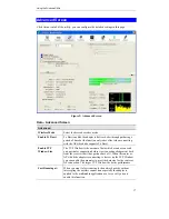
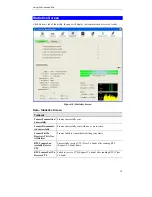
Page 23: ...sfully Frames successfully sent Frames Retransmit ted successfully Frames successfully sent with one or more reties Frames Fail To Receive ACK After All Retries Frames failed to transmit after hitting retry limit RTS Frames Suc cessfully Receive CTS Successfully receive CTS Clear To Send after sending RTS Request To Send frame RTS Frames Fail To Receive CTS Failed to receive CTS Request To Send af...

Page 24: ...mes received successfully Frames Receive With CRC Error Frames received with CRC error Frames Dropped Due To Out of Resource Frames dropped due to resource problem Duplicate Frames Received Frames received more than twice Reset Counter Click the button to reset counters to zero ...

Page 25: ...ions transmitted over Wi Fi WMM adds prioritized capabilities to Wi Fi networks and optimizes their performance when multiple concurring applica tions each with different latency and throughput requirements compete for network resources Click the check box and then click Apply button to apply this function to the system WMM Power Save Enable Click the check box and select the desired type of power...

Page 26: ...s WMM function and then enter the MAC address of the adapter which wants to connect with the remote system Timeout Value The utility performs time outs so that the program does not sit idle waiting for input that may never come Set a value to apply to the system with WMM Apply Click this button to save the changes you made Tear Down Click this button will disconnect the selected Direct Link Setup ...

Page 27: ...igure 12 WPS Screen Data WPS Screen WPS WPS AP List It displays the information of surrounding APs with WPS IE from last scan result List information includes SSID BSSID Channel ID Device Password ID and Security Enabled Rescan Click this button to update information on surrounding wireless network Information Display the information about WPS on the selected network List information includes Auth...

Page 28: ...e Profile Page of utility if exist If there is an empty profile page the driver will select any non security AP Export Profile Export all credentials to Profile Delete Click to Delete an existing credential And then select the next credential if exist If there is an empty credential the driver will select any non security AP PIN Start to add to Registrar using PIN configuration method If STA Regis...

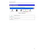
Page 29: ...Using the Windows Utility 25 Radio on off Screen Yu can turn the radio signal on off by clicking this button Figure 13 Radio on off The radio signal is on The radio signal is off ...

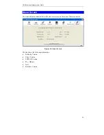
Page 30: ...Screen This screen displays details of the traffic sent or received on the current Wireless network Figure 14 About Screen This tab shows the following information RaConfig Version Driver Version EEPROM Version Phy_ Address Date Firmware Version ...

Page 31: ...02 11b Operating Channels 11 for North America 13 for Europe and Japan Operating Frequency 2 4 2 4835 GHz Modulation Technique 802 11g OFDM 802 11b CCK QPSK BPSK Media Access Protocol CSMA CA Operating Voltage 5V 5 Transmit Power 802 11g 13 5 1 dBm 802 11b 17 1 dBm Security WPA WPA2 128 bit TKIP AES encryption 40 64 128 bit WEP shared key encryption 802 1x and EAP TLS and PEAP authentication OS Re...

Page 32: ...ate only with Wireless Stations which are set to Infrastructure mode BSS ESS BSS A group of Wireless Stations and a single Access Point all using the same ID SSID form a Basic Service Set BSS Using the same SSID is essential Devices with different SSIDs are unable to communicate with each other ESS A group of Wireless Stations and multiple Access Points all using the same ID ESSID form an Extended...

Page 33: ...can join WEP WPA PSK Both WEP and WPA PSK are standards for encrypting data before it is transmitted This is desirable because it is impossible to prevent snoopers from receiving any data which is transmitted by your Wireless Stations But if the data is encrypted then it is meaningless unless the receiver can decrypt it WPA PSK is a later standard than WEP and is more secure WPA2 PSK This is a lat...

Page 34: ...D Wireless Stations should use the same SSID ESSID as the Access Point they wish to connect to Alternatively the SSID can be set to any or null blank to allow connection to any Access Point Security The Wireless Stations and the Access Point must use the same settings for Wireless security Disabled WEP WPA PSK WPA2 PSK WPA WPA2 If Wireless security remains disabled on the Access Point all stations...

Page 35: ...The safety advice in the documentation accompanying the products shall be obeyed The conformity to the above directive is indicated by the CE sign on the device The ALLNET ALL0233 Wireless USB Dongle conform to the European Directives R TTE 1999 5 EC and EC Low Voltage Directive 2006 95 EC This equipment meets the following conformance standards EN 301 489 1 V1 6 1 2005 09 EN 301 489 17 V1 2 1 200...

Page 36: ...t off and on the user is encouraged to try to correct the interference by one of the following measures Reorient or relocate the receiving antenna Increase the separation between the equipment and receiver Connect the equipment into an outlet on a circuit different from that to which the receiver is connected Consult the dealer or an experienced radio TV technician for help IMPORTANT NOTE To compl...

Reviews: