www.SereneLifeHome.com
2
www.SereneLifeHome.com
6
www.SereneLifeHome.com
7
PARTS DESCRIPTIONS:
ACCESSORIES PACK CHECK LIST:
INSTALLATION
1. Take out the Main Body (#1), Base (#7), Base Cover (#6) , accessories bag from
the cartons.
2. Put the main body up-side-down (Fig. A). Fixed the Connection Board (#2) with
Screw (#3) on the main body (#1) . Then Fix the Clamping Board (#4) with Screw
(#5) on the Connection Board (#2) . Put the plug and power supply cord through
the holes on the center of Base Cover (#6) and Base (#7). Then slide Base Cover
(#6) , Base (#7) and Washer (#10) with Screw (#11) onto main body respectively.
3. Put the power cord into the sink of the base. Then fix it with Camping Board
(#5) and Screw M4*35.
4. Fix the cover (#16) with the Screw M4*20 (#14).
OPERATIONS:
1. Plug in the unit to a socket. Make sure the power supply is same as rated.
2. LED indicator light stars flashing showing the heater is on standby. Press Mode
button on control panel to switch on the heater. The heater will start on the low
setting, each press of the Mode button will cycle the heater onto the medium
setting, high setting and then back to the low setting.
3. Press Swing Button on the control panel or remote controller to operate the
Oscillation.
4. Press TIMER button on control panel or remote control to choose the timer
between 0-9 hours. “
0
” means the timer is off. Each press of the Timer button
will cycle the timer from “
0
”-”
9
”.
5. When the heater is no longer required, switch off, using the off button on the
remote control or the control panel and unplug the unit.
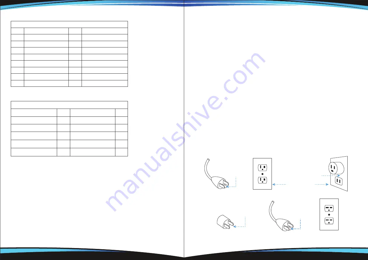
GROUNDING INSTRUCTIONS:
This heater is for use on 120 volts. The cord has a plug as shown at A in Figure
below. An adapter as shown at C is available for connecting three-blade grounding-
type plugs to two-slot receptacles. The green grounding lug extending from the
adapter must be connected to a permanent ground such as a properly grounded
outlet box. The adapter should not be used if a three-slot grounded receptacle is
available.
Parts Descriptions:
No.
Part Name
No.
Part Name
1
Main Body
9
Screw M4*28
2
Connection Board
10
Washer
3
Screw M6*8
11
Screw M6*35
4
Clamping Board
12
Remote Controller
5
Screw M6*27
13
Control Panel
6
Base Cover
14
Screw M4*20
7
Base
15
Plug
8
Camping Board
16
Cover
Accessories Pack Check List:
Accessory Name
Qty
Accessory Name
Qty
Allen Key
1
Washer
2
Screw M6*8
2
Remote Controller
1
Screw M6*27
2
Screw M4*28
2
Camping Board
1
Screw M6*35
2
Cover
1
Screw M4*20
2
Grounding Methods
Metal Screw
Ground cover
Outlet Box
Grounding Pin
A
B
Grounding Pin
Grounding Means
C
D
ADAPTER