www.SereneLifeHome.com
2
www.SereneLifeHome.com
6
www.SereneLifeHome.com
7
No.
Part Name
No.
Part Name
1
Screw M4*28
12
Joint Board
2
Plug
13
Screw M6*27
3
Base Cover
14
Tapping Screw ST4*12
4
Lower Body
15
Mode button
5
Screw M6*20
16
Remote control receiver
6
Washer
17
Standby Button
7
Base
18
Indicator Light
8
Base Bracket
19
Remote controller
9
Upper Body
15
Tapping Screw ST4*12
10
Power Supply Cord
20
Table
11
Cord Clip
Allen Key
1
Screw M6*27
8
Screw M6*20
2
Screw M4*28
2
Washer
2
Cord Clip
1
Joint Board
2
Tapping Screw ST4*12
4
PARTS DESCRIPTIONS:
ACCESSORIES PACK CHECK LIST:
INSTALLATION
1. Unpack and take out both upper body and lower body together.
2. Put Lower Body up-side-down (Fig. A). Fix Base cover (#3) onto Lower Control
Box. Then slide Base Cover (#3) , Base (#7) and Washer (#6) onto Base Bracket
(#8) respectively, and fix it well with Screw M6*20 (#5).
3. Lay Lower Body vertically (Fig. B). Put Upper Body on top of Lower Body.
Get the plug (#2) and power supply cord (#10) through the holes on the center
of Base Cover (#3) and Base (#7). Clip the power supply cord (#10) with Cord
Clip (#11) and fix it onto Base (#7) with Screw (#1) (Fig C).
4. Fix Upper Body and Lower Body with Joint Boards and Screw M6*27 (Fig.D).
5. As shown in Fig. E. Fix the table(#20) with tapping screw ST4*12(#14).
OPERATIONS:
1. Plug in the unit to a socket. Make sure the power supply is same as rated.
2. Press Switch to switch on the power. Heater is shifted to Standby mode.
Power Indicator Light (#18) starts flashing.
3. Press Select button (#15) to turn on one or both heating elements as desired.
Indicator Light (#18) will light up accordingly.
4. Press (#17) button to shift the heater to Standby mode.
5. Press Switch again to cut off the power totally.
GROUNDING INSTRUCTIONS:
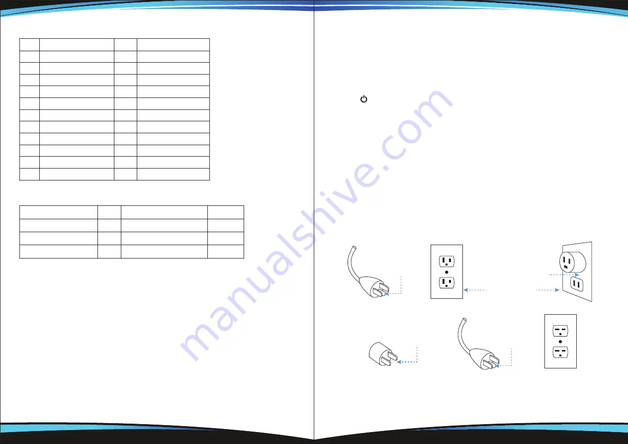
This heater is for use on 120 volts. The cord has a plug as shown at A in Figure
below. An adapter as shown at C is available for connecting three-blade grounding-
type plugs to two-slot receptacles. The green grounding lug extending from the
adapter must be connected to a permanent ground such as a properly grounded
outlet box. The adapter should not be used if a three-slot grounded receptacle is
available.
Grounding Methods
Metal Screw
Ground cover
Outlet Box
Grounding Pin
A
B
Grounding Pin
Grounding Means
C
D
ADAPTER


