background image

3

3

Power Consumption

Model Feature

Brightness

Current draw (idle)

Model: Seriline AB Cidron

LED-Bar

Backlight

12VDC

24VDC

SC93100-MDEB

STD 13.56MHz/125KHz/2.4GHz with keypad

Low

Low

90 mA

47 mA

Medium

Low

90 mA

47 mA

SC93110-MDEB

STD 13.56MHz/125KHz/2.4GHz without 
keypad

Low

Low

90 mA

47 mA

Medium

Low

90 mA

47 mA

SC93200-MDB

SLIM 13.56MHz/2.4GHz with keypad

Low

Low

34 mA

18 mA

Medium

Low

34 mA

18 mA

SC93210-MDB

SLIM 13.56MHz/2.4GHz without keypad

Low

Low

34 mA

18 mA

Medium

Low

34 mA

18 mA

The above values are excluding heater consumption which is variable and depending on 

configuration settings. Default value is 220 mA at 12VDC but can be configured in 20 mA 

intervals from minimum 120 mA to maximum 300 mA. When the heater is set in automatic 

mode, the heater will be activated when the internal temperature of the reader is below +1°C, 

the heater will automatically deactivate when the internal temperature e5°C. 

Depending on the heater consumption setting the time it will take for the reader to 5°C 

will vary- a higher power consumption setting will reduce the time required to heat the reader.

Current draw (idle) is defined as reader connected to power, no LED’s lit, buzzer is not 

sounding and no reading of credential or key pressing is processed by the reader. Current 

draw (peak) is defined as reader powered with both backlight and LED frame lit (Yellow), 

buzzer is sounding and reader is reading a credential while simultaneously a key pressing is 

processed.

Summary of Contents for Cidron Slimline VG3

Page 1: ...1 1 CIDRON Installation guide Cidron Slimline Reader...

Page 2: ...rs LED Green Red and Yellow Bi color Backlight in blue color Buzzer Power supply 9 30VDC Input Output 4 input for LED and buzzer and 2 configurable General Purpose Input Output GPI O The GPI O s are p...

Page 3: ...can be configured in 20 mA intervals from minimum 120 mA to maximum 300 mA When the heater is set in automatic mode the heater will be activated when the internal temperature of the reader is below 1...

Page 4: ...ont cover 2pcs Terminal connector 8 pin 2pcs Installation screws 2pcs Screw plugs 1pc Cable strip 1pc Fixing screw 1pc Quick installation guide Package content Please note that all pictures in this ma...

Page 5: ...5 5 20 cm In order to facilitate installation a cable length of 20cm is recommended...

Page 6: ...6 6 Ensure that the installation plate is fixed in the correct direction i e the arrows pointing upwards...

Page 7: ...tamper switch bulb of the installation plate is flat to be able to push the bulb for correct tamper alarm functionality If it is not flat enough you will find accessories in this manual that will assi...

Page 8: ...reader make sure to use a flat headed screw with a maximum height of 2 8 mm and a maximum diameter of 7 8 mm on the screw head Make sure not to tighten the screws too hard as doing so will deform and...

Page 9: ...9 9 Make sure to place the terminal connectors with the fastening screws facing towards you P3 Blue socket P4 Black socket...

Page 10: ...o each respective pin and also to GND The general purpose input output will only be activated if so applied in the reader configuration 4 RS 485 OSDP requires twisted pair cable K LED BZ R LED G LED D...

Page 11: ...cable is left in between the reader module and the installation plate Use the enclosed cable strip to fix the cable in the cord grip It is recommended to connect the the wires to the terminal connecto...

Page 12: ...12 12 When installing the reader to the mounting plate ensure that the reader pin header contact perfectly aligns with the terminal connector block...

Page 13: ...er the image above and make sure it is fitted correctly In order to do so allign and fit the top snap fastening apply and main tain pressure on the top of the front cover while sliding the front cover...

Page 14: ...14 14 To secure the front cover to the reader use the supplied fixing screw and fix it into the installation plate through the front cover...

Page 15: ...he front cover from the installation plate by inserting the tip of the tool into the slot at the bottom of the front cover and move the tool upwards This will release the front cover without damaging...

Page 16: ...Overview programming of reader Resetting the OSDP secure channel see page 20 Changing authentication card see page 19 Setting the reader in programming mode see page 17 Configuring the reader see pag...

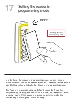
Page 17: ...to indicate that it is now in programming mode The Reader is in programming mode for 10 seconds If no other pro gramming card is presented within this time the reader will return to normal mode When a...

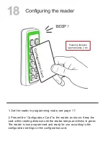
Page 18: ...ard to the reader as shown Keep the card within reading distance until the reader beeps and blinks in green The reader is now programmed and ready for use according to the configuration settings on th...

Page 19: ...ard within reading distance until the reader beeps and blinks in green The reader is now reprogrammed to only be set in programm ing mode by the new Authentication Card The old Authentication Card is...

Page 20: ...allation mode Card to the reader as shown Keep the card within reading distance until the reader beeps and blinks in green The reader has now reset the secure channel encryption keys to installation m...

Page 21: ...er open the SAM socket by unlocking and opening the lid Then place the SAM into the socket lock it into place by closing the lid and sliding it into locked position MIFARE SAM AV2 SIM Card Software IS...

Page 22: ...22 22 CIDRON Accessories Cidron Slimline Reader...

Page 23: ...sed for example when installing readers in environments where the installation surface is uneven or and external wiring at the same side as the reader Distance plate Slimline Matte black part no SC929...

Page 24: ...here additional cover is needed to hide old installation holes or on uneven surfaces Can also be used with external wiring on the same side as the reader Distance plate large Slimline Matte black part...

Page 25: ...25 25 Used to increase accessibility as well as visibility of the keypad Matte black part no SC9293 S Matte white part no SC9293 V Distance plate angled 10 Slimline...

Page 26: ...cessibility as well as visibility of the keypad Recommended height is 900mm center of reader above the ground floor Matte black part no SC9292 S Distance plate angled 33 Slimline Screws and screw plug...

Page 27: ...e reader and helps it withstand violence by absorbing and redirecting external forces away from the reader Can be retro fitted to already installed readers Vandalization protection Slimline Screws and...

Page 28: ...recommended combination when external wiring is needed together with the vandalization protection Can also be used for covering up old installation holes Distance plate large Vandalization protection...

Page 29: ...lender format When installing readers in intense sunny conditions the white version SC9901 V is recommended to use as a shading accessory to provide an environ ment for the reader without direct inten...

Page 30: ...e compressed air in between the buttons to remove dust and dirt and after that Isopropyl alcohol can be used with a piece of fabric to rub in between the buttons and the reader exterior Cleaning instr...

Page 31: ...on readerfamily are intended for Sale to professional security companies and installation by experienced security professionals Seriline AB can not provide assurance that any entity or person buying o...

Reviews: