Length after assembly
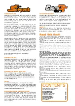
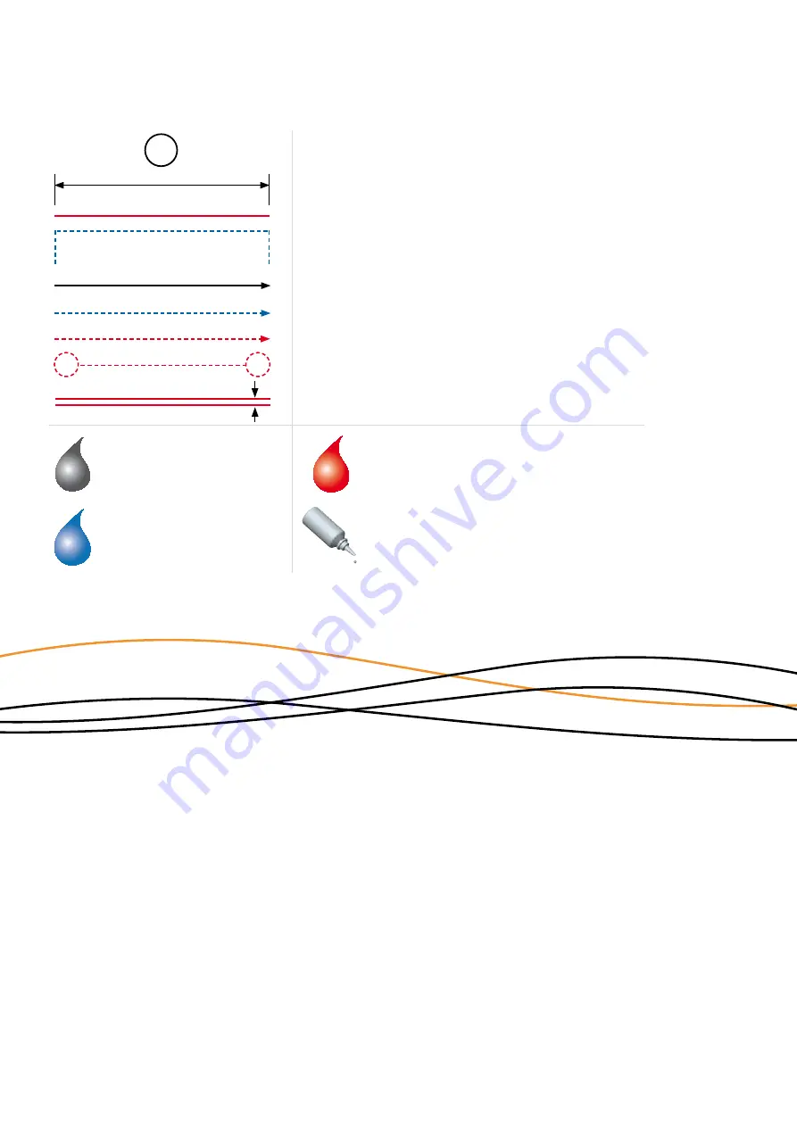
Each step contains a variety of numbers, lines, and symbols. The numbers represent the order in which the
parts should be assembled. The lines and symbols are described below.
Assembly path of one item into another
Group of items (within lines) should be assembled
first
Direction the item should be moved
Glue one item to another
Press/Insert one item into another
Connect one item to another
Gap between two items
Step number; the order in which you should
assemble the indicated parts
1
USING THE MANUAL
Apply graphite grease (Grey)*
Apply CA Glue (Red)*
(*Items not included.)
Apply threadlock (Blue)*
Apply silicone oil
ASSEMBLY INSTRUCTIONS
Summary of Contents for Cobra GT 3.0
Page 1: ...INSTRUCTION MANUAL REFERENCE GUIDE...
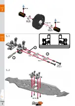
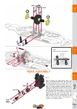
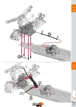
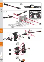
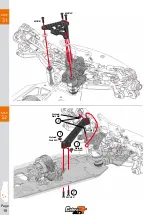
Page 11: ...Page 11 STEP 16 STEP 17 M4X12 M3x12 M3x22 1 2 Nylock Nut M3 Nylock Nut M3 Nylock Nut M3...
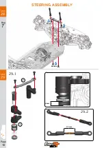
Page 16: ...Page 16 STEP 28 STEP 29 M4X10 M4X10 M4X10 21 mm 29 1 29 2 4mm 1 2 Bag 7 STEERING ASSEMBLY...
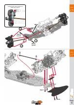
Page 21: ...Page 21 STEP 37 STEP 38 M2x10 5x8x2 5 5x8x2 5 M3x20 1...
Page 22: ...Page 22 STEP 39 STEP 40 NOT INCLUDED NOT INCLUDED M3x8 M3x8 M3x8 M3x3 M3x3 M3x3 1 2 3...
Page 23: ...Page 23 STEP 41 STEP 42 M4x12 M4x12 M4x12 M4x12 M3x3...
Page 30: ...Page 30 STEP 54 STEP 53 2x14 M2x10 M2x10 2x14 2 2 2 3 3 1 1 WHEELS AND TYRES NOT INCLUDED...
Page 41: ...www serpent com info serpent com Cobra GT 3 0 manual v1...

