background image

26

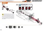
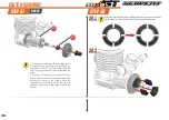
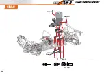
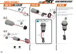
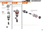
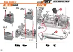
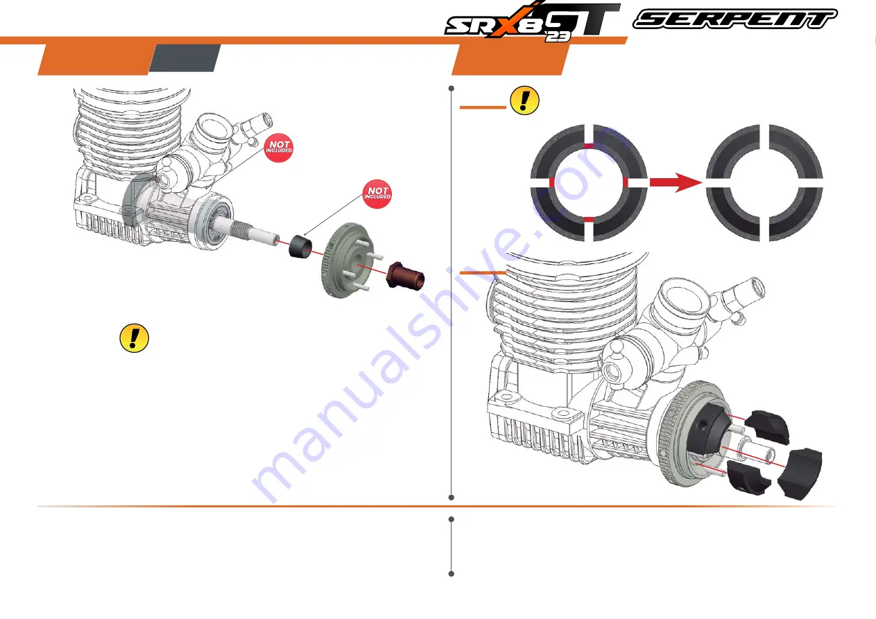
clutch assembly

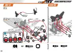
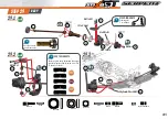
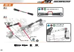
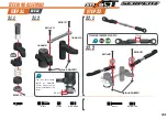
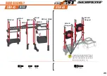
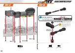
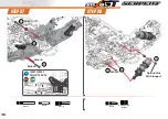
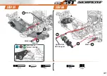
STEp 37

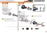
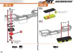
STEp 38

BaG 12

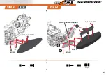
Before to assemble clutch shoes, carefully remove the red area and smoothen 

the cut surface in order to have four clutch shoes with the same shape.

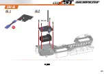
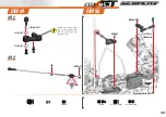
1-  To align the clutchgears with the 2-speed gears, 

it may be needed to use shim(s) 6x8x0.5mm (for 

6mm shaft) or 7x8x0.5 (for 7mm shaft) behind the 

cone. This you can see only after assembling the 

clutch. 

2-  The  holes  in  the  side  of  the  flywheel  can  be 

used to block the flywheel (with short allen tool) 

through the bottom of the chassis, when the 

engine/clutch is mounted in the car. It’s easier to 

tighten or loosen the pre-load on the clutch spring 

that way.

38.1

38.2

Summary of Contents for Cobra SRX8 GT

Page 1: ......

Page 2: ...possible Additional info may be published in our website www serpent com or you may ask your dealer or the Serpent distributor for advice or email Serpent direct info serpent com The Serpent Facebook...

Page 3: ...eck very well Apply a small amount of cyano glue Use wear protection for eyes and hands Detail view to explain assembly or order of parts better Default set up This symbol indicates the default setup...

Page 4: ...1 2 2 2 1 1 2 3 1 2 Add just enough oil to cover the large gear before assembling the small satellite gears and cross pins Use the silicone oil supplied in the kit For the correct cst value please ch...

Page 5: ...e crosspin do NOT overfill Use the siliconeoilsuppliedinthekit Forthecorrectcstvaluepleasecheckthedefaultsetupsheet 1mm Use a digital scale to measure the exact amount of oil in the diff Differential...

Page 6: ...default adjustment screw them untill the screws will be be leveled with the hole as in the right pictures 2 Adjust the M4x4 screw to minimise the gap between the shoes and the bell but still spinning...

Page 7: ...STEP 7 STEP 8 7 1 7 2 8x11x0 2 8x11x0 1 8x11x0 2 8x16x5 8x16x4 M3x8 2 5x8 2 5x8 M3x8 M3x18 Flanged 1 3 2 8x11x0 2 8x16x5 M3x18 Flanged 8x14x4 Flanged 8x14x4 Flanged 8x14x4 Flanged 8x16x4 8x11x0 1 M3x...

Page 8: ...8 central assembly STEP 9 M4x8 M3x6 M3x8 M3x6...

Page 9: ...9 STEP 10 STEP 11 M3x12 M3x6 M3x6 M3x3 M3x3 4x8x3 3x6x0 5 1 1 2 11 1 11 2 10 mm Note the throttle linkage assembly M3x12 M3x6 M3x6 M3x3 3x6x0 5 4x8x3...

Page 10: ...10 REAR ASSEMBLY STEP 13 STEP 12 BAG 3 M4x10 M4x12 M3x10 M3x10 REAR ANTISQUAT INSERTS CHART 1 1 2 M4x10 M3x10 M4x12...

Page 11: ...ttention When you assemble the diff with too much initial play the gears will not run in properly and may wear quickly After 1 or 2 hours of running the car re check the gear mesh between the ring gea...

Page 12: ...BAG 4 12 STEP 15 REAR TOEININSERTSCHART 1 1 2 3 M4x10 M4x10 STEP 16 M2 5x6 M2 5x6 15 1 15 2 34 mm ANTIROLL BAR ROD LENGTH Tighten anti roll bar cap until there is no play and it moves freely M2 5x6...

Page 13: ...BAG 5 13 STEP 17 STEP 18 17 1 17 2 M3X3 M3X3 M4X20 M3X3 5X8X2 5 Flanged M3x3 5X8X2 5 Flanged 1 1 DIFF INSERTS CHART LOW MID HIGH HIGH MID LOW M4x20 2 3 3 4 13x16x0 1 13x16x0 1 M2 5x4 M2 5x4...

Page 14: ...14 STEP 19 19 1 19 2 M3x8 M3x8 M3x22 M3x18 1 M3x22 M3x18 M3x8...

Page 15: ...m 1 25mm Nylock Nut M3 M5x4 M3x8 M3x8 3x13 4 3 5 6 2 3x17 Nylock Nut M3 8x16x5 13x19x4 M5x4 BAG 6 Note the correct coupler assemby REAR DEFAULT WHEELBASE SHIMS 8x11x0 1 20 2 20 3 20 1 REAR UPRIGHT ROL...

Page 16: ...16 21 1 21 2 STEP 21 M3x14 M3x22 3 2x7x0 5 Nylock Nut M3 1 4 3 2 3 5x7x0 5 Nylock Nut M3 REAR CAMBERLINK DEFAULT POSITION 16 3 mm REAR CAMBERLINK LENGTH M3x14 M3x22...

Page 17: ...front ASsEMBLY 17 BAG 7 STEP 22 M4X10 1 2 M4x10 STEP 23 M4x12 M3x10 M3x10 M4x12 M3x10 FRONT REAR INSERTS...

Page 18: ...lay the gears will not run in properly and may wear quickly After 1 or 2 hours of running the car re check the gear mesh between the ring gear and the pinion All parts should have run in properly now...

Page 19: ...G 8 19 FRONT SUSPENSION KICKUP INSERTS M4x10 1 3 2 M4x10 STEP 26 STEP 25 25 1 25 2 M2 5X6 M2 5X6 34 mm ANTIROLL BAR ROD LENGTH Tighten anti roll bar cap until there is no play and it moves freely M2 5...

Page 20: ...20 5X8X2 5 Flanged M3x3 5X8X2 5 Flanged STEP 27 STEP 28 27 1 27 2 1 1 2 M3x3 M3x3 M3x3 M4x20 M3x16 M3x12 DIFF INSERTS CHART LOW MID HIGH HIGH MID LOW M4x20 M3x12 2 3 3 4 5 5 13x16x0 1 13x16x0 1 M3x16...

Page 21: ...6x5 13x19x4 M5x4 M3x10 M3x3 Note the correct coupler assemby 3 2 Nylock Nut M3 1 M3x3 29 3 29 2 1 2 2 3 Steering arm 2 is included in the kit STEERING ARMS Caster angle is easily adjustable changingf...

Page 22: ...22 STEP 30 30 1 30 2 M3x18 Flanged M3x14 3 2x7x0 5 Nylock Nut M3 1 2 3 5x7x0 5 Nylock Nut M3 13 7 mm FRONT CAMBERLINK LENGTH FRONT CAMBERLINK DEFAULT POSITION M3x14 M3x18 Flanged...

Page 23: ...x0 5 3x6x0 5 M3x12 M3x20 M3x20 The servo saver spring should be preloaded 4 5mm Also notice the correct orientation of the collar Nylock Nut M3 Nylock Nut M3 32 1 32 2 17 mm 4 5 mm M2x10 M3x12 3x6x0 5...

Page 24: ...0 Note correct orientation of the outer steering balljoints Nylock Nut M3 Flanged Nylock Nut M3 Flanged 1 1 2 2 6x10x3 M3x20 3x7 5x1 Conical 3x7 5x1 Nylock Nut M3 Flanged Note correct position of the...

Page 25: ...25 STEP 35 STEP 36 M3x12 M3x12 M3x8 M3x3 M3x3 Nylock Nut M3 Nylock Nut M3 M3x12 M3x3 M3x8 M3x12...

Page 26: ...e 2 speed gears it may be needed to use shim s 6x8x0 5mm for 6mm shaft or 7x8x0 5 for 7mm shaft behind the cone This you can see only after assembling the clutch 2 The holes in the side of the flywhee...

Page 27: ...one and a half turns 3 Fine tune the setup of your clutch on the track according to your driving style track and weather conditions Place 5x8x0 1 and or 5x8x0 3 shims to achieve a small amount of end...

Page 28: ...28 STEP 41 M3x14 M3x14 M4x6 M5x12 Flanged M3x14 M4x6 M5X15 Flanged...

Page 29: ...6 M2x6 M2x6 M3x8 BAG 13 M3x16 Flanged M3x16 Flanged M3x16 Flanged STEP 42 Useenoughservospacerssobothservos are flush with the bottom of the radiotray posts Thiswillpreventtheservototouch the chassis...

Page 30: ...30 STEP 44 STEP 45 M3x10 M3x12 M3 Plastic Nut Flaged 45 1 45 2 Use tape to mount the battery to the plastic support M3x12 M3 Plastic Nut Flanged M3x10...

Page 31: ...31 STEP 46 46 1 46 2 M2x10 M2x10...

Page 32: ...Conical M4x10 3x7 5x1 Conical Nylock Nut M3 Check how many teeth your servo spline has 23 24 or 25 and use the right lever 6 5 7 mm STEERING LINK LENGTH Between differnet servo brands there could be...

Page 33: ...EP 50 3x7 5x1 Conical Check how many teeth your servo spline has 23 24 or 25 and use the right lever 49 1 49 2 3x7 5x1 Conical Nylock Nut M3 M3x6 M3x6 3x6x0 5 M3x3 4x8x3 4x8x3 Nylock Nut M3 M3x3 4x8x3...

Page 34: ...5 1 2 1 2 Insert the o ring inside the spring collar SHOCKS LENGTH Measure the shock length fully extended 27mm 1 Fill up with sillicone oil fully using the silicone oil supplied in the kit For the c...

Page 35: ...4 2 Push the membrane into the shock cap 1 Bleed push the shock rod all the way in slowly to allow excessive oil to escape 2 With shockrod fully in close fullu the shock cap Assemble the spring and sp...

Page 36: ...36 STEP 57 STEP 58 Nylock Nut M3 Flanged M3x25 FRONT SHOCKS DEFAULT POSITION M3x25 M4x18 M3x12 M4x16 1 2 3 2 3 1 Nylock Nut M3 Flanged M4x16 M3x12 M4x18...

Page 37: ...37 STEP 59 STEP 60 Nylock Nut M3 Flanged M3x25 REAR SHOCKS DEFAULT POSITION M3x25 1 2 3 3 1 Nylock Nut M3 Flanged M4x18 M3x12 M4x16 M4x16 M3x12 2 M4x18...

Page 38: ...38 final ASSEMBLY BAG 14 STEP 61 STEP 62 M3x6 M5x4 M3x12 Flanged M3x6 M5x4 M3x10 M3x12 Flanged M3x10 M3x10 M3x12 Flanged 61 1 62 2 61 3...

Page 39: ...39 BAG 15 STEP 63 STEP 64 Nylock Nut M3 Nylock Nut M3 Nylock Nut M3 Nylock Nut M3 Flanged M3x10 M3x12 M3x12 Nylock Nut M3 2 1 3 M3x10 M3x12 Nylock Nut M3 Flanged...

Page 40: ...40 Nylock Nut M3 STEP 65 STEP 66 Nylock Nut M3 M3x10 3 2x14 2x14 M2x10 M2x10 M2x10 M3x10 2x14 M2x10 M3x10 M3x10...

Page 41: ...41 STEP 67 2x14 2x14 M2x10 M2x10 2x14 M2x10...

Page 42: ...42 STEP 68...

Page 43: ...ARBOX exploded view 45 MID exploded view 46 REAR exploded view 47 FRONT exploded view 48 STEERING exploded view 49 RADIO exploded view 50 CLUTCH exploded view 51 SHOCKS exploded view 52 engine and exh...

Page 44: ...600200 110211 600214 600214 601059 110127 110432 110502 601060 110502 600200 110211 600421 110115 601067 601062 601062 601250 HTD diff set 44T SRX8 GT V2 601251 HTD diff gear 44T SRX8 GT V2 601280 HTD...

Page 45: ...T SL8 XLI 903733 2 speed gear 57T XLI Gen2 903771 2 speed gear set 6 XLI Gen2 903636X opt 903732 opt 903637X opt 903733 opt 903638X 903734 903729 110118 110118 110122 110508 110200 601248 903731 11043...

Page 46: ...02138 600226 110101 601004 110167 601041 600880 1639 600762 600120 1639 600829 600744 600748 600829 600988 mid exploded view 601042 Brake lever fr rr alu SRX8 GT 601266 Chassis set 4mm SRX8 GT 601267...

Page 47: ...ar2 7mm 600684 Antirollbarrear3 0mm 600484 Antirollbarspacer3mmalu 2 600485 Pivotballthreadedantirollbaralu 2 600896 WishboneinsertcarbonRRLowerV2SRX8 600851 Wheelhexagon0mmlight 2 SRX8 600852 Wheelhe...

Page 48: ...600852 Wheelhexagon 1mmlight 2 SRX8 600881 Antirollbarfront3 0mm 600887 WishboneinsertcarbonFRLower SRX8 2 600888 WishboneinsertcarbonFRUpper SRX8 600965 Antirollbarfront2 2mm 600966 Antirollbarfront...

Page 49: ...RX8 GT 2 110127 601036 110402 110402 110402 110402 110402 110402 601036 601037 601022 110112 601025 110125 110125 600751 600751 110415 1321 110415 600999 601023 110441 110441 600753 600812 110188 6003...

Page 50: ...120 600361 110415 110108 600361 600500 600500 110116 1639 1639 601033 600227 902138 600227 601040 600178 600178 110402 110146 110146 110402 601260 110109 110104 110104 601263 601261 110102 110102 1101...

Page 51: ...642 opt 903641 903643 opt 601169 opt 903796 opt 903640 Centax gear pinion alu 18T XLI 903642 Centax gear pinion alu 20T XLI 903643 Centax gear pinion alu 23T XLI 903645 Centax gear pinion alu 25T XLI...

Page 52: ...2 600598 Spring Fr Rr Purple 811GT 21lbs 600599 Spring Fr Rr Yellow 811GT 29lbs 600600 Spring Fr Rr White 811GT 31 5lbs 600357 Membrane webbed silicone 4 600875 Shock top gasket 4 SRX8 600850 Shock c...

Page 53: ...53 engine and exhaust 601159 Enginemount bottom magnesium SRX8 GT 2 601160 Enginemount top magnesium SRX8 GT 2 110106 110174 601030 110178 601031 601160 opt 601159 opt 600740 110122 110148 600773...

Page 54: ...143 110143 110112 600335 110194 600769 600335 600411 110145 600115 110441 600835 600768 600184 601017 110183 110183 110112 110441 600184 110143 110197 110197 601014 110194 600769 600835 600768 601253...

Page 55: ...GT 601269 Aero bumper set SRX8 GT 601276 Side bodymount set SRX8 GT 110219 110219 110183 600222 600222 110188 110188 601026 110402 601239 601239 601239 601239 600297 opt 600297 opt 110127 600263 60102...

Page 56: ...SRX8 GT 23 SPARE PARTS SRX8 GT 23 OPTIONALS PARTS SERPENT TOOLS SERPENT MERCHANDISING TEAM SERPEnT NETWORK...

Page 57: ...SERPENT SOCIAL MEDIA www facebook com SerpentMRC SERPENT WEBSITE AND BLOG www serpent com www teamserpent com www dragon rc com SERPENT PROMO PAGES http promo serpent com...

Page 58: ...Manual SRX8 GT 23 83626 1...

Reviews: