background image

3

hOW TO USE ThE maNUal

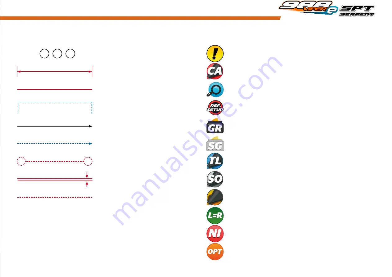
Each step contains a variety of numbers, lines, and symbols. The numbers represent the order in 

which the parts should be assembled. The lines are described below.

Each step contains a variety of symbols described below.

ICONS DESCRIpTION

lINES DESCRIpTION

Assembly path of one item into another

Detail view to explain assembly or order of parts better.

Group of items (within lines) should be 

assembled first

Default set-up: This symbol indicates the default setup.

Glue one item to another

Silicone grease: apply a small amount of grease to the parts shown.

Direction the item should be moved

Grease: apply a small amount of grease to the parts shown.

Left and right parts should be assembled in the same way.

Connect one item to another

Thread lock: apply a small amount on the parts shown. Before to apply the threadlock, 

make sure to degrease the parts very well, as otherwise the threadlock will not work.

Gap between two items

Silicone oil: use the indicated silicone oil for the shocks and differentials.

Parts or items not included in the kit.

Optional part, not standard in the kit.

Carefull, read and check very well.

Step number; the order in which you should 

assemble the indicated parts

1

3

2

Apply a small amount of cyano glue. Use wear protection for eyes and hands.

Length after assembly

Press/Insert one item into another

Oil: apply a small amount of oil to the parts shown.

OIL

IL

O

OI

OIL

Summary of Contents for Viper 988e

Page 1: ......

Page 2: ... com The Serpent Facebook Twitter and Youtube pages give additional means of support and communications Safety Read and take note of the Read this First section before proceeding to assemble the car kit This car kit is intended for persons aged 16 or older Read this first This is a highly technical hobby product intended to be used in a safe racing environment This car is capable of speeds in exce...

Page 3: ... moved Grease apply a small amount of grease to the parts shown Left and right parts should be assembled in the same way Connect one item to another Thread lock apply a small amount on the parts shown Before to apply the threadlock make sure to degrease the parts very well as otherwise the threadlock will not work Gap between two items Silicone oil use the indicated silicone oil for the shocks and...

Page 4: ...bag 1 4 rear assembly STEP 1 M4x8 M4x8 REAR ROLL CENTER INSERTS CHART FRONT REAR 1 2 ...

Page 5: ...5 STEP 3 STEP 2 M3x6 M3x8 M3x5 M3x8 M3x6 M3x5 REAR ANTIROLL BAR ROD LENGTH 32 5mm M4x10 M4x10 ...

Page 6: ...bag 2 6 STEP 4 REAR ROLL CENTER INSERTS CHART FRONT REAR 1mm 1mm M4x8 M4x8 1 2 3 4 M4x8 M4x8 STEP 5 ...

Page 7: ...REAR SOLID AXLE EXCENTERS Note that the rear solid axle excenters are not symetrical and are market with L left and R right LEFT RIGHT Use the central slot as starting position REAR BELT TENSION 12x18x4 M3x10 M3x8 12x18x4 1 1 3 4 M3x8 M3x10 12x18x4 2 ...

Page 8: ...8 STEP 8 M3x8 M3x8 M3x8 M3x6 M3x6 1 2 3 ...

Page 9: ...M3x10 2 3 2 1 1 1 REAR ANTIROLL BAR ASSEMBLY 5X8X2 5 M3x3 5x8x2 5 Do not tighten the M3x3 setscrews until the step 9 2 Fully tighten the M3x3 setscrews after adjusting the rear antiroll bar play to the minimum 9 2 M3x3 M3x10 ...

Page 10: ... 10 10 1 10 2 10 3 1 Note orientation of the outside wheel axle shim 2 Note position of the lever spring 12x15x0 25 12x18x1 Conical 12x18x4 M3x4 3x22 12x18x4 12x15x0 25 12x18x4 2 5x12 M3x4 3x22 1 1 3 4 5 2 2 2 5x12 ...

Page 11: ...11 STEP 11 3 3 mm 3 mm REAR TRACK WIDTH ...

Page 12: ...12 11 mm REAR CAMBERLINK LENGTH STEP 12 12 1 M3x20 1 2 4 4 1 M3x8 M3x20 12 2 REAR CAMBERLINK DEFAULT POSITION 3 2 M3x8 ...

Page 13: ...bag 4 13 front assembly STEP 13 M4x8 14 1 M4x8 M4x8 M2 5x8 12x18x4 12x18x4 12x18x4 1 2 2 M2 5x8 14 2 STEP 14 1 ...

Page 14: ...14 STEP 15 Use the central slot as starting position FRONT BELT TENSION M3x10 M3x10 M3x10 ...

Page 15: ...8 mm M3x6 M3x5 M3x6 M4X12 M4X12 2mm 1mm M4x12 16 3 Front lower suspension and shocks brackets Serpent 988 alows to move front bottom arms 3 mm in NARROW and out WIDE To maintain the same shock angle use the suspension bracket and shock bracket as shown here WIDE NARROW 1 2 2 ...

Page 16: ...16 STEP 17 5x8x2 5 M3x3 M3x12 M3x3 17 1 17 2 Front anti roll bar assembly 5x8x2 5 M3x3 M3x3 3 3 mm FRONT DOWN STOPS 2 3 17 3 1 1 M3x8 M3x12 M3x10 ...

Page 17: ...bag 6 17 STEP 18 FRONT SUSPENSION INSERTS CHART INSIDE OUTSIDE RIGHT RIGHT RIGHT LEFT LEFT LEFT MID 3x6x1 M3x10 M4x4 2 2 1 1 FRONT CASTER DEFAULT SPACERS 2mm 1mm 2mm M4x4 M3x10 3x6x1 ...

Page 18: ...18 STEP 19 STEP 20 M3x6 M3x6 M3x6 M3x5 SERVOSAVER ACKERMANN INSERTS FORWARD MID REARWARD 6x10x3 M4x8 M4X8 6X10x3 6X10x3 M3x5 ...

Page 19: ...TEERING BLOCK INSERTS CHART LEADING NEUTRAL TRAILING M3x12 21 2 M3x8 M3x6 RIGHT LEFT 2 5x12 12x15x0 25 5 pcs 12x18x0 3 12x18x4 12x18x4 M3x4 3x20 5 6 4 2 3 1 1 21 3 ACKERMANN POSITION Note position of the lever spring 12x15x0 25 12x18x1 Conical 12x18x4 2 5x12 M3x4 M3x8 M3x6 3x20 ...

Page 20: ...20 STEP 22 STEP 23 6 8 mm 7 mm FRONT CAMBER AND TRACK WIDTH STEERING TRACKROD LENGTH 45 5 mm 23 1 23 2 ...

Page 21: ...2 Flanged M3x12 Flanged M3x8 M3x5 M3x5 M3x6 Check how many teeth your servo spline has 23 24 or 25 and use the right lever 3x6x1 3x6x1 3x5x2 STEP 25 M3x16 5x10x4 3x5x2 5x10x4 M3x5 M3x16 Use double sided tape to mount the RX and the transponder to carbon bracket 3x6x1 ...

Page 22: ...22 STEP 26 STEERING TRACKROD LENGTH 73 5 mm 26 1 26 2 ...

Page 23: ...bag 9 23 STEP 27 M4x8 M4X8 ...

Page 24: ...24 STEP 28 M2 5x5 28 1 28 3 28 2 M3x5 6x12x4 6x8x0 3 6x10x3 M3x5 6x10x3 6x12x4 M2 5x5 6x8x0 3 ...

Page 25: ...25 STEP 29 M3x6 Flanged M3x8 2 3 1 M3x6 Flanged M3x8 ...

Page 26: ...26 STEP 30 BELTS ASSEMBLY DETAIL VIEW M3x16 5x8x2 5 Nylock Nut M3 5x8x2 5 Flanged 5x8x2 5 Flanged 5x8x2 5 M3x16 Nylock Nut M3 ...

Page 27: ...bag 10 27 STEP 31 STEP 32 M3x10 M3x10 M3x10 M3x10 M3x10 3x6x1 3x6x1 M3x8 M3x5 M3x10 M3x8 3x6x1 M3x5 M3x10 ...

Page 28: ...28 STEP 33 M5x4 M4x10 M5x4 M4x10 ...

Page 29: ...bag 11 29 battery and esc ASSEMBLY STEP 34 4S BATTERY CONFIGURATION 6S BATTERY CONFIGURATION optional default M3x8 M3x8 M3x8 M3x8 M3x8 M3x6 M3x8 M3x8 M3x8 M3x8 M3x6 M3x6 M3x6 M3x8 M3x6 M3x8 ...

Page 30: ...30 STEP 35 4S BATTERY CONFIGURATION 6S BATTERY CONFIGURATIONoptional default M3x8 M3x8 M3x8 M3x8 M3x8 M3x8 M3x8 M3x8 Nylock Nut M3 Nylock Nut M3 Nylock Nut M3 Nylock Nut M3 Nylock Nut M3 Nylock Nut M3 ...

Page 31: ...31 STEP 36 4S BATTERY CONFIGURATION 6S BATTERY CONFIGURATION optional default M3x10 M3x8 Nylock Nut M3 2 1 1 M3x10 Nylock Nut M3 M3x8 M3x10 M3x8 Nylock Nut M3 2 1 1 M3x10 Nylock Nut M3 M3x8 ...

Page 32: ...32 STEP 37 4S BATTERY CONFIGURATION 6S BATTERY CONFIGURATION optional default M3x6 M3x6 M3x6 M3x6 M3x6 M3x6 M3x6 M3x6 3x5x2 3x5x2 3x5x2 3x5x2 ...

Page 33: ...33 STEP 38 4S BATTERY CONFIGURATION 6S BATTERY CONFIGURATION optional default M3x6 M3x6 M3x6 M3x6 M3x6 M3x6 3x5x2 3x5x2 3x5x2 M3x12 ...

Page 34: ...34 STEP 39 39 1 39 1 39 2 39 2 BATTERY ROD LENGTH 5 mm BATTERY ROD LENGTH 4S BATTERY CONFIGURATION 6S BATTERY CONFIGURATION default optional 7 mm ...

Page 35: ...35 STEP 39 4S BATTERY CONFIGURATION detail view 6S BATTERY CONFIGURATION detail view default optional ...

Page 36: ...36 STEP 40 4S BATTERY CONFIGURATION 6S BATTERY CONFIGURATION default optional Use double sided tape to mount the ESC to the carbon bracket Use double sided tape to mount the ESC to the carbon bracket ...

Page 37: ...some silicone oil during the assembly Use some silicone oil during the assembly For the correct piston holes please check the default setupsheet Insert the o ring inside the spring collar Note the correct orientationofthe shock spacers Note the correct position of the o ring R2 3 R2 3 R2 3 front rear STEP 42 ...

Page 38: ...into the shock cap 1 Fill up with sillicone oil fully using the silicone oil supplied in the kit For the correct cst value please check the default setupsheet 2 Extend the shockrod fully 3 Move the shockrod slowly up and down to let ALL air bubbles escape 4 Close top only 3 4 1 Bleed push the shockrod all the way in slowly to allow excessive oil to escape 2 Close the shock cap completely front fro...

Page 39: ...x8 Nylock nut M4 M2 5x8 M2 5x8 M4x12 1 2 3 3 FRONT SHOCKS DEFAULT POSITION Nylock Nut M4 46 1 46 2 Note that the picture shows two diffrent insert options Assemble the same type in both sides Take as default the closed one M3x8 M4x8 M2 5x5 STEP 46 M3x6 ...

Page 40: ...40 STEP 47 STEP 48 M3x5 REAR SHOCKS DEFAULT POSITION M3x10 M3x10 M3x6 M3x10 M3x10 Do not overtighten the M3x10 screws to prevent binding M3x5 M3x6 M3x10 ...

Page 41: ...41 STEP 49 49 1 49 2 M3x10 M3x6 M3x6 M3x6 Flanged M3x6 Flanged 1 1 2 2 M3x10 M3x6 Flanged M3x6 M3x4 M3x4 M3x4 ...

Page 42: ...42 STEP 50 4S BATTERY CONFIGURATION 6S BATTERY CONFIGURATION default optional 4S BATTERY DETAIL VIEW 6S BATTERY DETAIL VIEW ...

Page 43: ...43 STEP 51 4S BATTERY CONFIGURATION 6S BATTERY CONFIGURATION default optional 4S BATTERY DETAIL VIEW 6S BATTERY DETAIL VIEW ...

Page 44: ...44 STEP 52 Wheels and tyres are NOT included ...

Page 45: ...ar exploded view 47 front i exploded view 48 front ii exploded view 49 mid i exploded view 50 mid ii exploded view 51 backbone exploded view 52 battery long exploded view 53 battery shorty exploded view 54 final exploded view 55 team serpent network 56 ...

Page 46: ...hole LF 2 160149 Shock onroad big bore piston 2 hole LF 2 160150 Shock onroad big bore piston 3 hole LF 2 160151 Shock onroad big bore piston 4 hole LF 2 160147 Shock onroad big bore bushing LF 4 160300 Spring white L23 2 3 13 2 160301 Spring yellow L23 2 8 16 2 160302 Spring orange L23 3 4 19 5 2 160303 Spring red L23 4 1 23 5 2 160304 Spring pink L23 4 0 28 2 160305 Spring blue L23 5 8 33 2 1603...

Page 47: ... 803198 808346 110504 903290 903686 110124 112125 903263 903685 110109 110124 903697 opt 903509 110504 110305 903503 903595 opt 903656 opt 903509 903666 110206 903395 903553 411063 411048 903567 903517 110433 903531 903609 opt 903231 903680 903680 903700 opt 903696 opt 110504 110120 110101 903392 903398 opt 110108 903395 903273 903687 110207 110108 110504 110305 904153 110109 903691 903684 902282 ...

Page 48: ...one insert carbon FR lw 2 903699 Wishbone FR lw L R hard S988 903676 903677 110177 808214 903231 903665 903699 opt 411063 110128 903626 411048 1650 110124 903544 opt 903628 opt 903582 opt 903676 903677 110177 804117 808214 110101 903691 903681 903681 903691 903665 903695 opt 110112 110112 110124 110124 903341 110116 903690 903688 opt 903689 opt 110116 903393 1311 903670 110108 9212 903651 opt 9035...

Page 49: ...03267 902271 110434 803198 808346 110112 903523 903524 110401 110115 803198 808346 903524 110504 110433 110504 110402 903266 903378 opt 110207 902281 902282 903601 opt 110101 110124 110108 903581 1652 903512 opt 903508 903516 903563 110118 808214 808214 903612 opt 110449 903702 opt 903570 110109 903678 411206 902128 903231 903508 1321 401025 904166 904146 1321 110157 401025 904146 110108 110108 90...

Page 50: ...4 Steering lever 23T alu 804215 Steering lever 24T alu 804216 Steering lever 25T alu 110145 904155 804214 opt 804215 opt 804216 opt 110157 110449 110510 901255 110110 904167 401687 401025 411206 904168 110104 110500 904157 110122 ...

Page 51: ...172 904156 110128 110404 904179 904178 opt 904180 opt 1321 1314 904144 904151 110166 1314 1321 904150 904144 904149 904183 904155 110402 110152 1312 1312 1311 110110 901255 110101 904178 Spurgear 56T 988E 904180 Spurgear 58T 988E ...

Page 52: ...ew 110151 904174 904175 opt 904176 opt 904177 opt 904158 904159 904159 110183 904159 110104 110109 110449 110109 110449 904164 110128 110183 904159 904163 904175 Pinion 20T 988E 904176 Pinion 21T 988E 904176 Pinion 22T 988E ...

Page 53: ...ed view 904171 904170 904161 904172 110402 110108 110108 904160 110104 902138 401721 411253 110410 110108 110410 411253 110183 110104 904161 110402 904162 110402 110108 904172 904161 904161 904160 110104 110183 110104 904171 ...

Page 54: ...3 110410 110117 904161 110410 411253 904170 904172 902138 401721 411253 110410 904169 110108 904169 904160 904161 110100 110108 110108 904172 904162 101122 110410 411253 904169 904161 110108 904160 904162 110402 904161 110122 110183 110183 110402 ...

Page 55: ... view 110109 909345 903619 903537 110172 903706 110115 903538 110109 903536 903706 903706 904184 1650 110108 808152 160152 110137 110128 903502 110403 1650 110136 903664 903663 110105 903619 110128 903521 110136 160152 ...

Page 56: ... NETWORK 988e SPARE PARTS www serpent com 904004 spares 988e OPTIONALS PARTS www serpent com 904004 Optionals SERPENT TOOLS www serpent com product Tools SERPENT MERCHANDISING www serpent com product Merchandising ...

Page 57: ...t com www dragon rc com www youtube com user SerpentMRC www twitter com SerpentMRC www plus google com SerpentModelcars posts www weibo com teamserpent SERPENT PROMO PAGES http promo serpent com SERPENT FACEBOOK GROUPS http promo serpent com indexfb htm SERPENT ADVANCED MANUALS http promo serpent com sam ...

Page 58: ...Manual 988e 57555 1 ...

Reviews: