ASSEMBLY
CY72 01/08
Assembly Section 3-3
© 2008 Alamo Group Inc.
ASSEMBL
Y
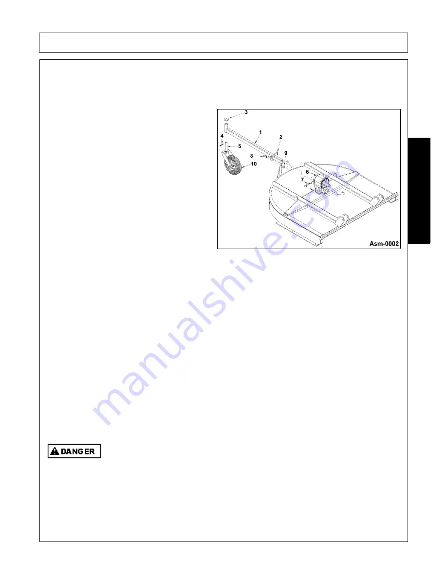
Tailwheel Assembly (Figure Asm-0002)
To assemble the Mower’s TailWheel, follow the procedures listed below.
Note
: Certain steps may have been
performed by the manufacturer before delivery.
1. Place a 1-1/2” flatwasher (3) on the shaft of the
caster fork & wheel assembly (5). Attach
assembly to tailwheel beam (1) by inserting
shaft through the large hole of the tailwheel
beam. The beam must be positioned with its
grease fitting on the opposite end of the
tailwheel. Note: A light coat of grease can be
placed on the shaft for easier installation. After
the shaft is completely inserted, place another
1-1/2” flat washer onto the shaft and retain by
inserting a cotter pin (4) through shaft above
the washer. Spread ends of cotter pin.
2. Slide tailweel positioning bracket (2) onto
tailwheel beam. Position the opposite end of
the tailwheel beam between the set of lugs in
the mid section of the mower deck behind the
gearbox. Align holes of the lugs and tailwheel
beam and retain with a 5/8” x 4” bolt (7) and 5/
8” locknut (6).
3. Place the mid section of the tailwheel beam
between the tailwheel beam support brackets at
the desired cutting height. Note: The rear deck
height is set by raising or lowering the tailwheel
beam. Raise the beam to reduce the height of
cut, lower the beam to increase the height of
cut. Retain the beam in this position by
securing the positioning bracket to support
braces with two 1/2” x 1-1/2” bolts (8) and 1/2”
locknuts (9).
4. Tighten all bolts, lockwashers, and nuts to the
recommended torque and grease fitting on end
of tailwheel beam until grease is visible on
either end of shaft.
Front and Rear Deflectors (Standard Equipment) and Chain Guards
(Optional Equipment at Extra Cost)
Front and Rear rubber-fabric Deflectors are Standard Equipment and Front and Rear Chain
Guards are optional . One type of guard must be installed (and maintained in good repair)
except for agricultural purposes only in areas where persons, vehicles, livestock, or other
property will not be endangered by thrown objects and where such safety equipment would
prevent the mower's reasonable performance of its assigned agricultural task.
Assy01-
Shielding
Summary of Contents for CY72
Page 7: ...Safety Section 1 1 2008 Alamo Group Inc SAFETY SECTION...
Page 27: ......
Page 28: ......
Page 29: ......
Page 30: ......
Page 31: ......
Page 32: ......
Page 33: ......
Page 34: ......
Page 35: ......
Page 36: ......
Page 37: ......
Page 38: ......
Page 39: ......
Page 40: ......
Page 41: ......
Page 42: ......
Page 43: ......
Page 44: ......
Page 45: ......
Page 46: ......
Page 47: ......
Page 48: ......
Page 49: ......
Page 50: ......
Page 51: ......
Page 52: ......
Page 53: ......
Page 54: ......
Page 55: ......
Page 56: ......
Page 57: ......
Page 58: ......
Page 59: ......
Page 60: ......
Page 61: ......
Page 62: ......
Page 63: ......
Page 64: ......
Page 65: ......
Page 66: ......
Page 67: ......
Page 68: ......
Page 69: ......
Page 70: ......
Page 71: ...Introduction Section 2 1 2008 Alamo Group Inc INTRODUCTION SECTION...
Page 75: ...Assembly Section 3 1 2008 Alamo Group Inc ASSEMBLY SECTION...
Page 83: ...Operation Section 4 1 2008 Alamo Group Inc OPERATION SECTION...
Page 125: ...Maintenance Section 5 1 2008 Alamo Group Inc MAINTENANCE SECTION...
Page 133: ......
Page 136: ...CY 72 SOM 01 08 P N 00757419C Printed U S A CY 72 ROTARY CUTTER...


