SerVision
MVG400 Installation Guide
Connecting Devices to the MVG400
16
If you want to connect the PTZ controllers of multiple cameras to the unit, only one of the controllers can use an
RS232 connector – the others must all use RS485 connectors. PTZ controllers for more than one RS232 camera
cannot be connected to the unit simultaneously.
If you connect multiple RS485 PTZ camera controllers, they should be daisy-chained to the
RS232/485
connector,
as described below. In this case, each camera in the chain must be given a different ID number. Please refer to your
camera's documentation for information about configuring its ID number. In addition, note that you can only create
an RS485 daisy chain if every link on the chain (i.e., every camera) uses the same PTZ protocol. Attempting to
connect cameras that use different protocols will prevent all of the cameras from working properly.
To connect an RS232 PTZ controller:
The RS232 controller cable should end with a female 9-pin RS232 connector.
•
If you are only connecting the RS232 PTZ controller to the unit, and are not connecting any RS485 PTZ
controllers, plug the 9-pin RS232 connector directly into the
RS232/485
connector on the rear panel of the
unit.
•
If you are also connecting one or more RS485 PTZ controllers to the unit, plug the 9-pin RS232 connector into
the RS232/485 adapter supplied with the unit.
To connect an RS485 PTZ controller:
Each RS485 controller cable should end with two wires.
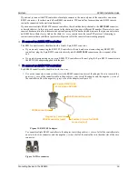
1. Use a wire connector to connect the wires to the RS485 connection wires of the adapter. Be sure to match the
positive (+) wire of the controller cable to the positive (+ red) wire of the adapter, and the negative (-) wire of
the controller cable to the negative (- grey) wire of the adapter (see figure 13).
Figure 13: RS232/485 adapter
To connect multiple RS485 controllers to the adapter, insert the positive (+) wires of all of the controllers into
one slot in the wire connector, and the negative (-) wires of all of the controllers into the other slot of the wire
connector.
Figure 14: Wire connector
RS485 connection wires
Plug into RS232/485
connector on MVG400
RS232 connector
Positive (+) wire for RS485
connector (red)
Negative (-) wire for
RS485 connector (grey)


