SerVision
MVG400 Installation Guide
Connecting Devices to the MVG400
23
For information about connecting sensors and activators to the IA 3126-2 relay board, and about connecting the
relay board to a power source, please consult the relay-board’s documentation.
NOTE:
If you are connecting less than 16 activators or 16 sensors to the relay board, be sure to connect them to
the relay beginning with the lowest connector, and do not leave open connectors between those that
you use. For example, if you are connecting 4 activators and 3 sensors, connect the activators to output
connectors 1-4 on the board and the sensors to input connectors 1-3 on the board.
To connect the IA 3126-2 relay board to the M VG400:
1. Set the ID of the relay board to
0
. (For information about how to do this, consult the relay-board
documentation.)
2. Connect the relay board to the
RS232/485
connector on the rear panel of the MVG400 unit in one of the
following ways:
•
•
•
If you are not connecting any RS485 PTZ controllers to the unit, using a 9-pin flat ribbon cable, connect
the RS232 connector of the relay board directly into the
RS232/485
connector.
•
•
•
If you are also connecting one or more RS485 PTZ controllers to the unit, using a 9-pin flat ribbon cable,
connect the RS232 connector of the relay board into the RS232 connector of the RS232/485 adapter
supplied with the unit. Connect the PTZ controllers to the adapter as explained under
Connecting PTZ
Controllers
, page 15. Then plug the adapter into the
RS232/485
connector on the unit.
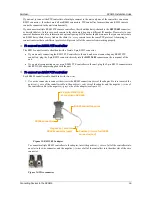
Figure 23: RS232/485 adapter
Note:
If you connect a relay board to the unit, you cannot connect any RS232 PTZ controllers or an ADAM
module to the unit. For additional information about connecting PTZ controllers to the unit, see
Connecting
PTZ Controllers
, page 15. For information about connecting an ADAM module to the unit, see
Connecting
Sensors Using an ADAM Module
, page 18.
Connecting Microphones
Up to two microphones can be connected to the unit, one active and one passive. When one or two microphones are
connected, you can hear and record sound along with video images. The sound from a microphone can be
associated with any or all of the cameras in the unit’s configuration. (For additional information, please refer to the
Embedded Video Gateway System Guide
.)
Microphones can be connected to one or both of the
Audio In
connectors (
Ain1
and/or
Ain2
). Passive
microphones, which require external amplification, must be connected to
Ain1
. Active (self-amplifying)
microphones must be connected to
Ain2
. Microphones with an output voltage of 1 Vrms or 1.41 Peak are
supported.
Plug into RS232/485 connector on
MVG400
RS232 connector


