background image

stepIM 

Scope Dashboard 

ServoStudio Reference Manual 

41 

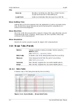
A sequential number for identifying the recorded sample. 

Time (ms) 

The time of the recorded sample. 

Recorded 
Variable 

Columns showing the names and values of the variables 
selected for recording. 


14.4.2


Measurements 

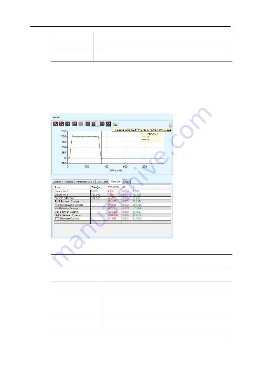
The 

Measure

 tab in the Scope screen presents several measurements from the 

data currently displayed in the chart.  

The values displayed change as you drag the cursors to different locations on the 
chart.  


Figure 


14-5.  ServoStudio – Scope Measurement Tab 

Cursor No.1 

X-axis = time (in ms); value of trace at the point 
crossed by cursor. 

Cursor No.2 

X-axis = time (in ms); value of trace at the point 
crossed by cursor. 

Cursor Difference 

Time difference between the two cursors. (Cursor 2 – 
Cursor 1) 

RMS/RMS 
Between Cursors


The root mean square for the entire recording; or the 
root mean square for the recording between the two 
cursors. 

Average/ 
Average Between 
Cursors 

The average value for the entire recording; or the 
average value for the recording between the two 
cursors. 

Summary of Contents for ServoStudio stepIM

Page 1: ...stepIM Introduction ServoStudio Reference Manual stepIM Manual Revision 1 1 Software Version 1 41 Firmware Version 0 0 2 79 ...

Page 2: ......

Page 3: ...laimer This product documentation was accurate and reliable at the time of its release Servotronix Motion Control Ltd reserves the right to change the specifications of the product described in this manual without notice at any time Trademarks All marks in this manual are the property of their respective owners Contact Information Servotronix Motion Control Ltd 21C Yagia Kapayim Street Petach Tikv...

Page 4: ...stepIM 4 ServoStudio Reference Manual ...

Page 5: ... 1 Current Limit 19 8 2 Velocity Limit 20 8 3 Position Limit 21 9 Inputs Outputs ____________________________________________ 22 9 1 Digital Inputs 22 9 2 Digital Outputs 23 9 3 Analog Input 23 10 Enable Faults _____________________________________________ 24 10 1 Drive Enable 24 10 2 Faults 25 11 Motion Operating Modes ____________________________________ 26 11 1 Profile Position Operation Mode 1...

Page 6: ......

Page 7: ...le setup configuration and tuning of the servo drive It also allows you to set certain parameters for the stepIM motor and the particular application in which the stepIM is used 1 2 Manual Format This manual describes the screens menus and functions in ServoStudio For detailed instructions on commissioning the stepIM refer to the stepIM User Manual ...

Page 8: ...tion 1 Download ServoStudio software from the Servotronix website or contact Technical Support 2 Install ServoStudio software on the host computer 3 When installation is complete start ServoStudio from the Windows Start menu or the shortcut on your desktop 2 3 Drive Selection When ServoStudio is first activated after installation it may prompt you to select the drive you are using Figure 2 1 Drive...

Page 9: ...ne Toggles ServoStudio communication with the drive off and on and indicates the state of the connection Offline mode ServoStudio does not attempt to communicate with the drive Online mode ServoStudio continually communicates with the drive to read parameters and status Note It is recommended to switch to Offline mode before physically disconnecting the drive or powering off the drive Enable Disab...

Page 10: ...on use F1 or the right click shortcut menu to activate Help for the currently selected field About Software version information Sidebar Contains a navigation menu to the various ServoStudio screens The sidebar can be hidden or displayed using the Arrow button Task Screen Displays various interactive screens for viewing setting and testing parameters and drive configurations These screens are descr...

Page 11: ...hrough and delete messages in the dialog box Right click New Messages on the status bar to delete all messages in the log Current Motor current Shows the equivalent motor current Object 6078h Velocity Motor velocity Shows the velocity of the motor according to the primary feedback Object 606Ch Position Motor position Shows the actual motor position according to the primary feedback Object 6064h Of...

Page 12: ...Exercise caution however as motor behavior will change If a parameter cannot be modified while the stepIM is enabled ServoStudiowill prompt you to disable the stepIM 3 3 1 Data Entry Throughout ServoStudio you will work with fields containing configurable read write drive parameters Whenever you begin entering a parameter value the field turns blue After entering or modifying a value press the Ent...

Page 13: ...er over a parameter field to view its description and CANopen object name Figure 3 3 Schematic Tooltip Some of the fields in these screens are read only Their values are entered automatically according to the motor defined in the Motor screen and or settings defined elsewhere in the software Other fields in these schematic screens are configurable read write After entering or modifying a value pre...

Page 14: ...hed to another drive To access an object start typing in the Find Object field As you begin typing an object number or name a list of possible matches appear Click on the object you want to modify and click Edit Object The object is copied to the Selected Objects table Click on the object s Value field to modify the value An object in gray text cell is read only and cannot be manipulated Right cli...

Page 15: ...e click on the drive s node ID in either the Communication screen or in the Switch to Drive menu in the status bar Figure 5 1 ServoStudio Communication Screen Bit Rate The stepIM is factory defined with default setting of CAN bit rate 1000 kps Connect The software attempts to connect to drive s defined by the search Go Offline To use ServoStudio without connecting to the drive click Go Offline Add...

Page 16: ...io Reference Manual IDs to Connect Displays the node IDs of all drives detected The green node ID indicates the drive with which ServoStudio is currently communicating To communicate with a different drive click on that drive s node ID ...

Page 17: ...nical Support when asking for assistance The Drive Information screen also provides access to the Firmware Download utility Figure 6 1 ServoStudio Drive Information Screen sensAR Drive Details Hardware defined Read only Shows the drive model and serial number and version numbers of the firmware and hardware Download Firmware Activates the installation procedure for new versions of drive firmware R...

Page 18: ... can be manipulated up a predefined factory setting Object 6075h Peak Current The peak rated current of the stepIM It can be manipulated up a predefined factory setting Object 2036h Temperature Control Board The temperature of the drive electronics board in Celsius degrees Read only Object 2044h Bus Voltage Limits Over Voltage Threshold Shows the level for detection of bus over voltage Range 11500...

Page 19: ...he current limit for your application Figure 8 1 ServoStudio Current Limit Screen Peak Current The peak rated current of the stepIM It can be manipulated according to factory defined limits Object 2036h Motor Rated Current The continuous current of the stepIM This value is obtained from the motor datasheet electronic nameplate It can be manipulated according to factory defined limits Object 6075h ...

Page 20: ...motor over the maximum allowed continuous energy it is calculated as follows I2T dt I Icont 2 Object 2033h 8 2 Velocity Limit The Velocity Limit screen contains a diagram that shows how the maximum velocity for the system is determined and enables you to set the velocity limit for your system accordingly Figure 8 2 ServoStudio Velocity Limit Screen Velocity Limit The maximum velocity of the stepIM...

Page 21: ...bject 6065h Position Window The error tolerance for declaring an in position state Object 6067h Hardware Position Limits Error The inputs that indicate whether position limits have been reached in the positive and negative direction Software Position Limits Software Position Limit Mode Enables and disables the use of software position limits 0 Software position limits disabled 1 Software position ...

Page 22: ...fset and to monitor the analog input Figure 9 1 ServoStudio I Os Screen 9 1 Digital Inputs The Digital Inputs pane in the I Os screen allows you to configure functionality and polarity of the digital inputs and to monitor the state of the digital inputs State A graphic element that toggles between green and red to reflect the on or off state of the actual input Name Identifies the specific input M...

Page 23: ... outputs State A graphic element that toggles between green and red to reflect the on or off state of the actual output Name Identifies the specific output Mode Defines the condition that will activate a specified digital output 9 3 Analog Input The Analog Input 1 pane in the I Os screen allows you to set the analog input properties and to monitor the input state Analog Offset The DC voltage offse...

Page 24: ... to move The Enable Faults screen graphically shows the conditions required for the drive to be enabled It allows you to clear faults and to activate the Software Enable switch As long as any light in the diagram is red the drive remains disabled When all lights are green the drive is enabled Figure 10 1 ServoStudio Enable Faults Screen ...

Page 25: ...ings tab displays a list of all faults and warnings currently in effect Displays a list of warnings Displays a list of faults that are preventing the drive from being enabled Warnings remain displayed until cleared by Clear Faults button provided the condition that caused the warning has been removed After a fault condition is removed the fault remains latched until cleared by any of the following...

Page 26: ...isplayed in the Motion screen varies according to the selected operation mode Using the Motion screen you can execute motion and view the actual values of current velocity and position ServoStudio displays the list of standard CiA 402 CAN operation modes Figure 11 1 ServoStudio Motion Screen CANopen Operation Modes Note CANopen Cyclic Synchronous Position operation mode 8 is not available in Servo...

Page 27: ...coder 0 position Executes an absolute position movement according to the acceleration deceleration settings Incremental Moves the motor the specified number of counts from its current location Executes an incremental position movement according to the acceleration deceleration settings Alternating Automatically reverses the direction of motion each time Start is pressed Target Position The destina...

Page 28: ... Value Velocity Velocity Demand Value Position Position Demand Value Object 6074h Object 606Bh Object 6062h 11 2 Profile Velocity Operation Mode 3 In the Motion screen select CANopen Operation Mode 3 Profile Velocity to display the schematic and parameters for work in Profile Velocity mode Figure 11 3 ServoStudio Motion Screen Serial Velocity Mode Profile Acceleration Acceleration value Object 608...

Page 29: ...que Operation Mode 4 In the Motion screen select CANopen Operation Mode 4 Profile Torque to display the schematic and parameters for work in Profile Torque mode Figure 11 4 ServoStudio Motion Screen Profile Torque Mode Current Command Sets the value of the current Object 6071h Current Start Sends the Current command to the motor Stop Stops the Current command Demand Values Current Torque Demand Va...

Page 30: ... graphic A graphic display representing the method selected for the homing process description A description of the selected homing method Homing Acceleration The value of acceleration and deceleration during the homing process Object 609Ah Fast Homing Speed The initial velocity used in the homing process during the search for limit switches home switches and hard stops Object 6099h sub index 1 Sl...

Page 31: ...stepIM Motion Operating Modes ServoStudio Reference Manual 31 Home Start Starts the homing process Stop Stops the homing process Homing Status Displays the current state of system homing Object 2090h ...

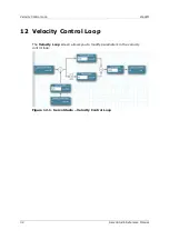
Page 32: ... Control Loop stepIM 32 ServoStudio Reference Manual 12 Velocity Control Loop The Velocity Loop screen allows you to modify parameters in the velocity control loop Figure 12 1 ServoStudio Velocity Control Loop ...

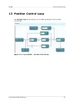
Page 33: ...osition Control Loop ServoStudio Reference Manual 33 13 Position Control Loop The Position Loop screen allows you to modify parameters in the position control loop Figure 13 1 ServoStudio Position Control Loop ...

Page 34: ...n is a dashboard for data recording and plotting Figure 14 1 ServoStudio Scope Dashboard The Scope screen allows you to perform the following tasks Configure recording settings record data from the drive and display the data according to your preferences Generate motion in order to record data related to that specific motion Commands can be sent to the drive via the Move Record and Plot buttons in...

Page 35: ...iable that can be recorded To add a variable to the list type the name of the variable in the blank cell in the first row and press Enter To define the variables that will actually be recorded select or clear the checkboxes Offset An offset value on the X axis that serves to separate overlapping traces on the chart or to move traces closer together for easier viewing and comparison Whenever an off...

Page 36: ...tion the cursor on the graph Variable values at the cursor point are displayed in a floating box Use the Measure tab to view additional variable values at the point marked by the cursor Select Cursor Displays a second cursor line Click on the graph to position the second cursor View in Excel Copies recorded data to a temporary CSV file and opens Microsoft Excel to display it 14 3 Chart Options The...

Page 37: ...the letter F is displayed next to the Chart Options button on the toolbar When Scale is frozen the letter O is also displayed if part of the trace is out of view Reset All Trace Offsets Resets the value of all offset values in the Record Variables list to 1 Whenever an offset is in effect a plus sign is displayed next to the variable name in the legend Grid Color by Trace If two grids are used rig...

Page 38: ... on different traces Set Trace Offsets This option is used to separate overlapping traces and improve the readability of the chart Right click on a specific trace and enter offset values Figure 14 3 Set Trace Offsets Dialog Box Hide Trace Right click on a specific trace and select Hide Trace to hide just one trace Trace Properties Set Trace Color In Chart Options Trace Options Allows you to define...

Page 39: ...ated Trace These options define how a fast Fourier transform FFT algorithm is performed on the selected trace Add Derivative Trace In Chart Options Trace Options Calculates and displays the derivative of the function FFT Trace In Chart Options Trace Options The FFT is performed on the selected trace and displays a graph that represents the frequency domain FFT Between Cursors In Chart Options only...

Page 40: ...ified low value to a specified high value Typically these values are 10 and 90 of the step command Still in development Show Overshoot Overshoot is when a signal exceeds its target Still in development 14 4 Scope Tabs Panels Motion Change operation mode and initiate motion using the Motion panel Refer to Motion Operating Modes Data Table A tabular view of the data generated by the recording Measur...

Page 41: ... as you drag the cursors to different locations on the chart Figure 14 5 ServoStudio Scope Measurement Tab Cursor No 1 X axis time in ms value of trace at the point crossed by cursor Cursor No 2 X axis time in ms value of trace at the point crossed by cursor Cursor Difference Time difference between the two cursors Cursor 2 Cursor 1 RMS RMS Between Cursors The root mean square for the entire recor...

Page 42: ...ServoStudio Reference Manual Min Lowest recorded value in the trace Max Highest recorded value in the trace Pk Pk The total span between the highest and lowest recorded values in the trace STD The standard deviation of the trace ...

Page 43: ...en Basic Settings Startup Default Screen The task screen that is displayed when ServoStudio is activated It can be any of the screens listed in the sidebar By default Drive Information is the default screen Show Splash Screen Defines whether the ServoStudio splash screen is displayed when ServoStudio is activated Language Select Language Defines the interface language options English Chinese Simpl...

Page 44: ...log files ServoStudio Version The version of the ServoStudio software Figure 15 2 ServoStudio Preferences Screen Advanced Settings Configuration Files The names and locations of files used by ServoStudio For Expert users only Advanced Operation Mode Refresh Rate of Data from Drive Sets the rate at which variable values are refreshed on screen This includes both user defined watched variables and s...

Page 45: ... can be edited using Notepad or any other text editor Restore Opens an Open dialog box Loads the parameters and values from a file on the host computer to the drive RAM Generate Report Opens the Report Generator dialog box Creates a set of CSV and TXT files within a zip file The file can be attached to an email that is automatically addressed to Technical Support You can change the address and sen...

Page 46: ...uration of your application even when the system is functioning properly When activated the Report Generator opens a dialog box that allows you to enter application and user information Figure 16 2 Report Generator The Report Generator creates a set of CSV and TXT files within a zip file and saves it in the default path c users owner Documents ServoStudio Reports History Send report by email Attac...

Page 47: ...stepIM Backup Restore ServoStudio Reference Manual 47 ...

Page 48: ......

Page 49: ...ServoStudio Reference Manual stepIM ...

Reviews: