
PARTS IDENTIFICATION
IMPORTANT! BEFORE FIRST USE:
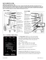
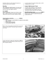
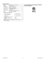
The grab handle/vacuum hose guide (see Fig. A) is shipped inside the filter basket (Fig. D). Remove the hose
guide from the basket and install it as shown using the four screws provided. Do not overtighten the screws. The
unit is now ready to be set up as an extractor or booster. Two Velcro straps are also enclosed in the filter basket
(Fig. D). Use these straps to secure the extractor hose when not in use.
Vacuum inlet
(from
extraction tool).
Gravity drain hose
.
Keep capped and clipped
into place when not in
use.
Grab handle/vacuum
hose guide
. Direct hose
through guide before use
to avoid tipping. See
“Before First Use”
below for installation
instructions.
Filter basket cover
latches
. Remove cover
by lifting latches.
Cover assembly
latches
(×4)
FIG. A: FRONT
Also included:
25 ft.
section of 2 in. vacuum
hose.
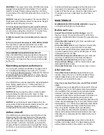
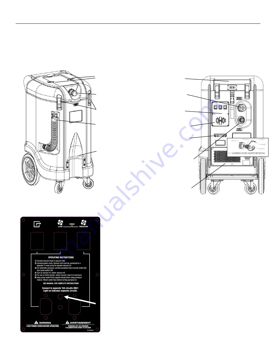
FIG. C: CONTROL PANEL DETAIL
P: Automatic pumpout switch.
Turn on to activate automatic pumpout
system.
NOTICE!
When automatic pumpout system is activated, sump
pump can turn on any time liquid is present in tank. Liquid may eject from
Pump Outlet with considerable force and cause injury. Always attach a drain
hose and place the end in a suitable drain before activating automatic
pumpout system.
A: Power cord socket.
Provides power to sump pump and blower 1.
B: Power cord socket:
Provides power to blower 2.
IMPORTANT! Secure power cords into sockets with lock.
1, 2: Vacuum blower switches.
LOW:
Blower 1 ON, Blower 2 OFF. Cord A required.
MEDIUM: Blower 1 OFF, Blower 2 ON. Cord B required.
HIGH:
Blower 1 ON, Blower 2 ON. Cords A and B required.
Independent circuit indicator light:
Glows bright green when the two cords
are properly connected to separate circuits. No light appears if a) the two cords
are connected to the same circuit or b) if only one cord is connected. When using
both power cords, do not operate the unit unless the green light is illuminated.
P
1
2
A
B
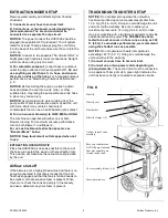
Power cord lock.
Secures
plugs in sockets.
Automatic
pumpout drain
outlet
. Pre-fitted with a 1½
in. outlet. To use a garden
hose, replace with the
supplied ¾ in. fitting (inset).
Keep capped when not in use.
Vacuum outlet.
Connect
to truckmount for use as
booster. Keep capped
when not in use.
Handle
Control panel
and
power cord sockets
.
Details in Fig. C.
Power cord retention
clips
. Secure cord(s) here
while using the unit.
HEPA exhaust filter grill
.
Thumbscrews allows easy
filter replacement.
FIG. B: REAR
SP004 HVE3000
3
Dri-Eaz Products, Inc.


