19
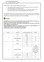
SESAMO
DUALCORE
C
power
6 (-)
7 (+)
1.
(opening control)
1
NO
2
2.
(safety closing)
10
NC
11
3.
(test)
8
NC
9
D
power
19 (-)
20 (+)
1.
(Safety opening)
17
NC
18
2.
(Test)
14
NO
15
NOTE: for more detailed information on the colors of the cables and terminals, refer to the
specific manual supplied with the sensor for the selected model.
DANGER: select and install the sensors to suit the architectonic design of the
doorway according to a thorough risk assessment in compliance with EN16005. If not, the
automatic movement of the doors can cause serious injury or damage to persons or
objects with the risk of fatal lesions.
SETTINGS AND CONNECTIONS FOR
RD100
VERSION
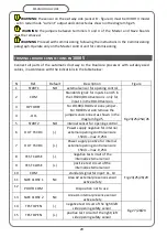
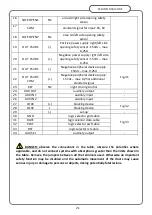
The arrangement of the components for the RD100 version automated system is that of fig.
5/A.
The connections to the peripheral devices must be made on the Master control panel (part.
S).
The Master and Slave control units must be connected together as shown in fig. 25
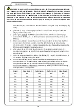
Parameters: set only on Master control unit:
• paramete
r
21
(Start2 input polarity) set to
1
(NC)
• parameter
27
(Aux In2 input polarity) set to
1
(NC)
• parameter
13 type
electric lock for RD100 version set to 4 (Bistable). To
complete the setting and keep the ENT button pressed for 5 seconds.
WARNING: for the RD100 automated system, the only electric lock that can be
installed is exclusively the bistable safety electric lock, which requires the setting of
parameter 13 to 4. During the setting, press and hold the ENTER button for 5", so as to
allow the MASTER board to acquire the parameter correctly; if no button is pressed, the
setting returns to default value 1 (normal electric lock).
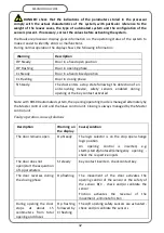
WARNING:
make sure that the Main Keys - detail J - Fig. 21 - are correctly inserted in
the respective control units; see the following table:
Control unit
Description
Master
Main key type SM (C2 indication on display)
Slave
Main key type SS (C3 indication on display)
Summary of Contents for DUALCORE LH100
Page 1: ...LH100 LH140 RD100 ENGLISH AUTOMATED SYSTEMS FOR SLIDING DOORS INSTALLATION MANUAL ...
Page 44: ...44 SESAMO DUALCORE Fig A Fig B ...
Page 45: ...45 SESAMO DUALCORE Fig 1 ...
Page 46: ...46 SESAMO DUALCORE Fig 2 ...
Page 47: ...47 SESAMO DUALCORE Fig 3 ...
Page 48: ...48 SESAMO DUALCORE WARNING Exit way ONLY for RD100 Fig 4 ...
Page 49: ...49 SESAMO DUALCORE Fig 5 ...
Page 50: ...50 SESAMO DUALCORE Fig 5 A ...
Page 51: ...51 SESAMO DUALCORE Fig 6 Fig 7 ...
Page 52: ...52 SESAMO DUALCORE Fig 8 Fig 9 ...
Page 53: ...53 SESAMO DUALCORE Fig 9a Fig 10 ...
Page 54: ...54 SESAMO DUALCORE Fig 11 Fig 12 ...
Page 55: ...55 SESAMO DUALCORE Fig 13 Fig 14 Fig 15 ...
Page 56: ...56 SESAMO DUALCORE Fig 16 Fig 16a ...
Page 57: ...57 SESAMO DUALCORE Fig 17 Fig 17a ...
Page 58: ...58 SESAMO DUALCORE Fig 18 Fig 19 Fig 20 ...
Page 59: ...59 SESAMO DUALCORE Fig 21 Fuses 6 3A T J ...
Page 60: ...60 SESAMO DUALCORE Fig 22 ...
Page 61: ...61 SESAMO DUALCORE Fig 23 1 Fig 23 2 ...
Page 62: ...62 SESAMO DUALCORE Fig 24 PARAMETER 30 1 ...
Page 63: ...63 SESAMO DUALCORE Fig 25 PARAMETER 30 1 Exit way ...
Page 64: ...64 SESAMO DUALCORE Fig 25 A ...
Page 65: ...65 SESAMO DUALCORE Fig 26 ...
Page 66: ...66 SESAMO DUALCORE Fig 27 PARAMETER 31 1 ...
Page 67: ...67 SESAMO DUALCORE Fig 28 PARAMETER 31 0 ...
Page 68: ...68 SESAMO DUALCORE Fig 29 ...
Page 69: ...69 SESAMO DUALCORE Fig 30 Fig 31 ...
Page 71: ...71 SESAMO DUALCORE Fig 33 ...
Page 72: ...72 SESAMO DUALCORE Fig 34 ...

