7
SESAMO
DUALCORE
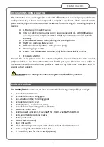
PREPARATIONS FOR INSTALLATION
The automated device is designed to work with different accessory and peripheral devices
configurations. Fig.4 shows an example of a complete installation where possible access
points are highlighted in the automated device box for connecting the following peripheral
devices:
A.
Left side opening safety sensor
B.
Internal safety sensor during closing and opening control - for RD100 version
use only a sensor compliant with EN 13849-1 performance level "d" Cat.2 for
exit ways
C.
External safety sensor during closing and opening control
D.
Right side opening safety sensor
E.
Differential switch (230Vac mains power supply)
F.
Operating logic selector
G.
Electric lock release lever (Optional, only if the electric lock is present)
I Emergency button
Prepare the access points inside the automated system to allow connection with external
peripheral devices. Use the notch on the head for the passage of the mains power cable, or
make one inserted in the aluminum profile as shown in fig. 34. Protect the cable with the
special rubber supplied.
DANGER: do not damage the cable during the described fixing activities.
PARTS DESCRIPTION
The
LH100 /LH140
automated systems consist of the following parts (ref. fig.1 and fig.5):
A-
extruded aluminum box
B-
extruded aluminum sliding guide
C-
anti-vibration rubber for sliding guide
D-
extruded aluminum cover
E-
brush (Optional, available in 3 sizes)
F-
extruded aluminum filling profiles (Optional)
G-
electronic control unit
H-
gearmotor with encoder - type 63x25 for LH100, type 63x55 for LH140
I-
belt support and tensioning device
J-
Battery (optional)
K-
electric lock (Optional)
L-
door limit switch
M-
adjustable carriages equipped with wheels and anti-derailment wheel
N-
belt coupling with toothed traction belt
P-
n° 1 matching part for electric lock (Optional)
Summary of Contents for DUALCORE LH100
Page 1: ...LH100 LH140 RD100 ENGLISH AUTOMATED SYSTEMS FOR SLIDING DOORS INSTALLATION MANUAL ...
Page 44: ...44 SESAMO DUALCORE Fig A Fig B ...
Page 45: ...45 SESAMO DUALCORE Fig 1 ...
Page 46: ...46 SESAMO DUALCORE Fig 2 ...
Page 47: ...47 SESAMO DUALCORE Fig 3 ...
Page 48: ...48 SESAMO DUALCORE WARNING Exit way ONLY for RD100 Fig 4 ...
Page 49: ...49 SESAMO DUALCORE Fig 5 ...
Page 50: ...50 SESAMO DUALCORE Fig 5 A ...
Page 51: ...51 SESAMO DUALCORE Fig 6 Fig 7 ...
Page 52: ...52 SESAMO DUALCORE Fig 8 Fig 9 ...
Page 53: ...53 SESAMO DUALCORE Fig 9a Fig 10 ...
Page 54: ...54 SESAMO DUALCORE Fig 11 Fig 12 ...
Page 55: ...55 SESAMO DUALCORE Fig 13 Fig 14 Fig 15 ...
Page 56: ...56 SESAMO DUALCORE Fig 16 Fig 16a ...
Page 57: ...57 SESAMO DUALCORE Fig 17 Fig 17a ...
Page 58: ...58 SESAMO DUALCORE Fig 18 Fig 19 Fig 20 ...
Page 59: ...59 SESAMO DUALCORE Fig 21 Fuses 6 3A T J ...
Page 60: ...60 SESAMO DUALCORE Fig 22 ...
Page 61: ...61 SESAMO DUALCORE Fig 23 1 Fig 23 2 ...
Page 62: ...62 SESAMO DUALCORE Fig 24 PARAMETER 30 1 ...
Page 63: ...63 SESAMO DUALCORE Fig 25 PARAMETER 30 1 Exit way ...
Page 64: ...64 SESAMO DUALCORE Fig 25 A ...
Page 65: ...65 SESAMO DUALCORE Fig 26 ...
Page 66: ...66 SESAMO DUALCORE Fig 27 PARAMETER 31 1 ...
Page 67: ...67 SESAMO DUALCORE Fig 28 PARAMETER 31 0 ...
Page 68: ...68 SESAMO DUALCORE Fig 29 ...
Page 69: ...69 SESAMO DUALCORE Fig 30 Fig 31 ...
Page 71: ...71 SESAMO DUALCORE Fig 33 ...
Page 72: ...72 SESAMO DUALCORE Fig 34 ...


