background image

SeTec-SKM03.2-Kunde 02TB21-F 

Page 1 of 23 


Line-Type Sensor Cable Alarm 

SKM-03.2 

DIN EN54-22:2015+A1:2020 


Technical Description 

Item no. BK83000 

VdS  G221005 


Securitas Electronic Security Deutschland GmbH 

SeTec Sicherheitstechnik 

Hauptstr. 40a 

82229 Seefeld 


Issue date: 25.02.2021 

Summary of Contents for SKM-03.2

Page 1: ...23 Line Type Sensor Cable Alarm SKM 03 2 DIN EN54 22 2015 A1 2020 Technical Description Item no BK83000 VdS G221005 Securitas Electronic Security Deutschland GmbH SeTec Sicherheitstechnik Hauptstr 40...

Page 2: ...1 3 1 4 Operating elements 11 3 1 5 Self hold alarm with reset function 12 3 2 Sensor cable description 14 3 2 1 Sensor element labelling 15 3 2 2 Packaging cable reel labelling 15 3 3 Termination uni...

Page 3: ...nfiguration S1 12 Table 6 Terminal assignment SKM 03 2 termination unit 17 Table 7 Terminal assignment SKM 03 2 connector unit 19 Table of Figures Figure 1 Block diagram SKM 03 2 system 5 Figure 2 Con...

Page 4: ...4 623 Parallel display for fire alarms DIN EN 54 22 2015 A1I A2I and CI approved VdS testing as per DIN EN 52 22 pending The sensor cable monitoring system enables early detection of a fire as well as...

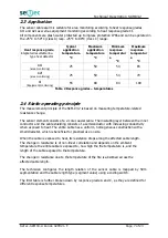
Page 5: ...talled under the ceiling when monitoring areas The cable being exposed to heat in the case of a fire changes the electrical properties of the cable which is detected by the control unit and triggers t...

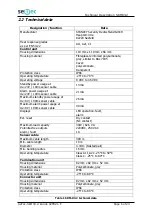
Page 6: ...1 mA Maximum standby power usage at UB 9V 100m sensor cable 26 mA Maximum alarm power usage at UB 9V 100m sensor cable 49 mA Displays LED operation fault alarm Ext reset Dry contact NC contact Maximum...

Page 7: ...rature related resistance change The sensor element consists of a 2 core coaxial cable The insulating layer between the inner conductor and the cable shielding consists of a semiconductor with increas...

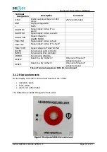
Page 8: ...d The function of the control unit is bundled on the SKM 03 2 control circuit board Optical indicators for operation fault and alarm are routed through a front panel and to the top of the front panel...

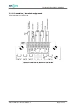
Page 9: ...Technical Description SKM03 2 SeTec SKM03 2 Kunde 02TB21 F Page 9 of 23 3 1 1 Connection terminal assignment All connections use terminal X1 Figure 2 Connecting the SKM 03 2 control unit...

Page 10: ...ut Active if no fault FAULT COM Signal voltage for FAULT NC NO OUTER Sensor cable outer conductor INNER Sensor cable inner conductor SHIELD Sensor cable shielding RESET2 Reset line dry contact 2 Only...

Page 11: ...dry contacts are rated 30W 62 5VA Contact Description ALARM NC Active if no alarm ALARM NO Active on alarm ALARM COM Signal voltage for ALARM NC NO FAULT NO Active on fault FAULT NC Active if no fault...

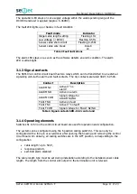
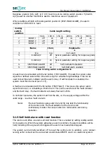
Page 12: ...sed to test the alarm indicator and the alarm relay If self hold alarm is enabled the system must then be reset see 3 1 5 A fault can be simulated with the S3 button TEST FAULT This moves the sensor c...

Page 13: ...ff This can be a negative effect in specific applications To be able to use the external reset the break off jumper must be broken off The break off jumper is a jumper between RESET1 and 2 Meaning it...

Page 14: ...ductor and the shielding of the coaxial cable The measurement results can be used to detect a short circuit and wire break as faults If the sensor cable is strained by heating beyond the permitted ran...

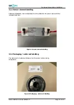
Page 15: ...ing Following installation the included label must be affixed to the sensor cable with the included cable ties Figure 4 Sensor element labelling 3 2 2 Packaging cable reel labelling The cable reel is...

Page 16: ...m 025 L housing The housing meets the relevant environmental requirements and is waterproof as per IP66 The termination unit connects to the open end of the sensor cable The actual sensor element can...

Page 17: ...board is identical to the terminal assignment of the control circuit board The sensor cable connects to terminal X1 Figure 7 Connection SKM 03 2 termination unit Terminal designation Description OUTER...

Page 18: ...The housing meets the relevant environmental requirements and is waterproof as per IP66 The connector unit is an optional accessory It can be connected to several sectioning points of the sensor cable...

Page 19: ...ard is identical to the terminal assignment of the control circuit board The sensor cable ends connect to terminals X1 and X2 Figure 9 Connection SKM 03 2 connector unit Terminal designation Descripti...

Page 20: ...nderground car park The sensor cable should be installed with cable clips or modular snap in clamps The cable must be between 10 and 20mm from the ceiling It must not come into contact with metallic s...

Page 21: ...20 pitch S1 0 5m to 2 5m from walls equipment or stored goods S2 max 7m between two parallel sensor lines max 2 x DH S3 10mm to 20mm from the ceiling 4 2 2 Room size from 30m flat roof over 20 pitch S...

Page 22: ...Kunde 02TB21 F Page 22 of 23 4 3 Sensor cable installation The sensor cable can be installed with the following clips OBO cable clip 2037 Item no BK52007 SeTec cable clip Item no BK83005 The recommend...

Page 23: ...tically resets DIP switch 6 position correct ON Alarm doesn t automatically reset DIP switch 6 position correct OFF Checking alarm release Press the TEST ALARM button on the PCB for 7 sec Checking fau...

Reviews: