background image


ST - II Series POWER SUPPLIES

USER INSTRUCTIONS

Introduction

These instructions detail the installation and operation requirements for the ST20-II & ST35-II 
power supplies. These have been designed for operation in RV’s providing a DC power system, 
with optional battery back up. 
The units operate from 240Vac and provide an isolated 13.65Vdc output at 20A and 35A 
respectively for powering the load and charging of batteries. All the necessary protection and 
operating features for the load and batteries are provided. An optional DC input is also provided to 
enable charging of batteries and powering of the load from an ex13.8V DC power source.
The units are fully enclosed ready for direct wall mounting. All connections are at the rear of unit 
providing convenient wiring and installation. User access to all load and battery fusing has been 
provided from the front of the unit.

Operation 

Safety:

 Refer to the installation section before operating. Correct installation is the most critical 

factor in ensuring the safe use of the power supply. If every consideration of these instructions has 
been satisfied the power supply will be safe to operate.

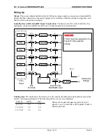
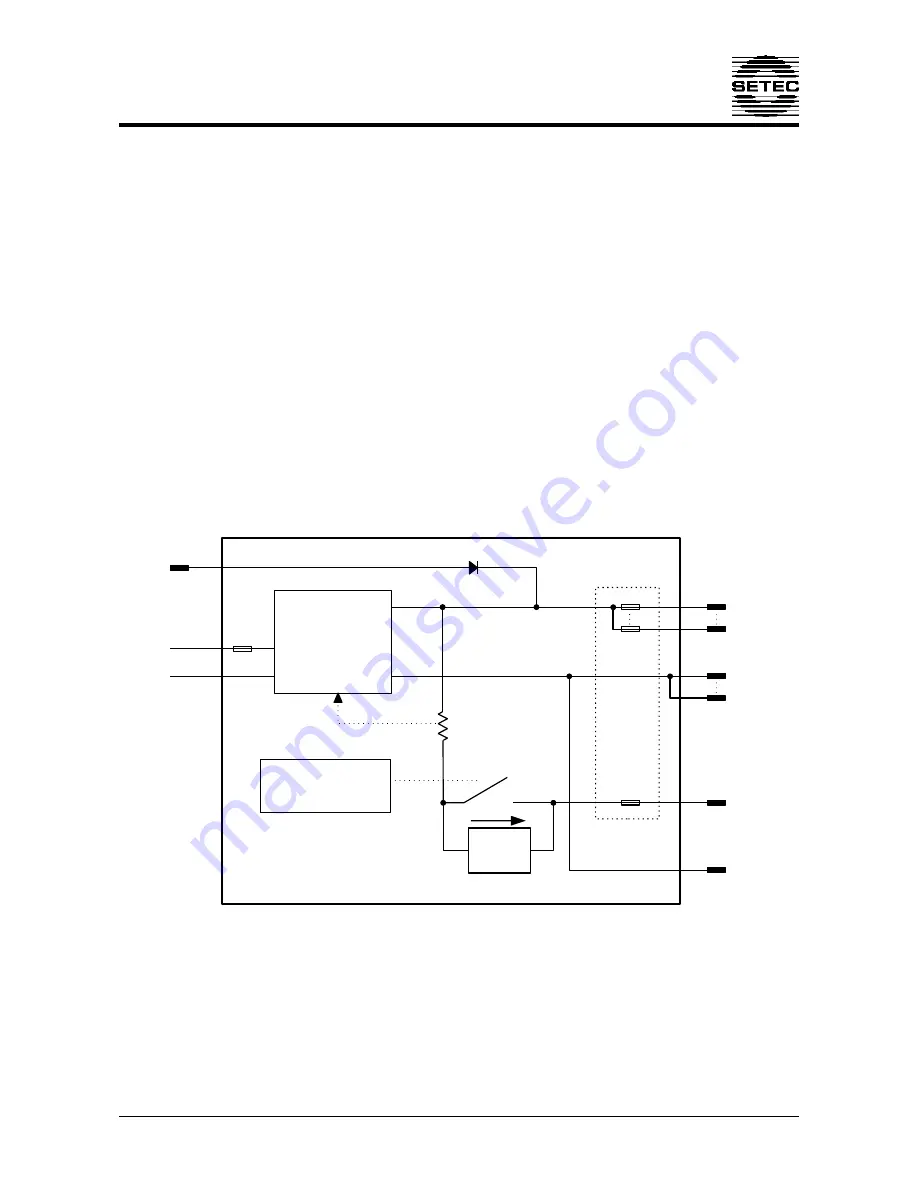
Functional Diagram:

Figure 1 Functional Block Diagram

Page 1 of 11

Doc 019244

AC Input

DC External
Input

Isense

5 x Load

Outputs

Battery

Output

Fuse Panel

AC / DC

Power Supply

Vadj

Battery Low Voltage
Disconnect circuit

0.8A

Trickle

+ve

-ve

+ve

-ve

Summary of Contents for ST20-II

Page 1: ...of the load from an external 13 8V DC power source The units are fully enclosed ready for direct wall mounting All connections are at the rear of unit providing convenient wiring and installation Use...

Page 2: ...battery will be charging at 0 8A When the battery voltage is sufficient 10 5V for first power up 11 5V and 11 7V for subsequent reconnection with and without mains respectively the LVD will connect th...

Page 3: ...ll shut down It will attempt to automatically restart every 5 seconds until such case that the fault is removed Fusing Each load circuit and the battery have been fused to provide fault protection and...

Page 4: ...shut down A minimum ventilation of 20 000mm2 to the outside world must be provided CAUTION Do not install unit in same compartment as batteries or flammable material such as petrol Ensure that the ins...

Page 5: ...ating QC connector suitable for cable size Connector pin out is shown below Cabling sizes DC cables must be sized to carry the maximum full load current and not exceed the system volt drop requirement...

Page 6: ...r supply terminal or negative chassis ground If battery is connected to chassis ensure a connection exist from chassis to Batt VE terminal of power supply Battery Disconnection Procedures Battery shou...

Page 7: ...servicing a battery disconnect the power supply Batteries are electrically alive at all times and must be treated with extreme caution They can supply high short circuit currents even if they appear d...

Page 8: ...tion 17V Over Current Protection ST20 II 20A to 25A load battery current ST35 II 35A to 38A load battery current Battery Current Limit 10A 1A ST20 II 15A 1A ST35 II Battery Connect Disconnect Connect...

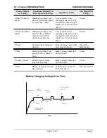
Page 9: ...A detailed description of the operational requirements for the charging algorithm is described below Present Output Set Voltage Conditions Required to Enter Operational State Operational State New Ou...

Page 10: ...oost charging mode active after resumption of mains input supply set 15 minute boost timer Vboost Vboost No mains input voltage is detected Boost charging mode while no mains is detected Vboost No Mai...

Page 11: ...or devices in close proximity 3m and as such do not guarantee that the power supply will not cause interference with devices such as TV s or radios The ST20 II 35 II have been designed with equipment...

Reviews: