background image

ST – II Series POWER SUPPLIES

USER INSTRUCTIONS

Batteries

When using batteries with this product always consult with the battery manufacturer for a detailed 
description of the installation, use and maintenance of the battery.
Ensure battery has being charged for several days before a major camping trip (Leave the power 
supply on for at least 2 – 5 days with battery connected). 
This product is suitable for charging 12V-Sealed Lead-Acid (SLA) batteries including Valve-
Regulated Lead-Acid (VRLA) batteries both Absorbed Glass Mat (AGM) and Gel batteries. 
Charging current is limited to 10A (ST20-II) and 15A(ST35-II).

CAUTION:

Ensure that there is good ventilation from the battery area.
Ensure that cable connections to batteries have the correct polarity and are protected against 
accidental short circuit.
Ensure that the shrouding supplied with the battery is fitted to the terminals
Provide visual notification that batteries are being used in area of use.
Before servicing a battery, disconnect the power supply. 
Batteries are electrically alive at all times and must be treated with extreme caution. They can 
supply high short circuit currents, even if they appear damaged. Take care that dropping or touching 
of metal objects onto the battery cell does not cause short circuits. Remove any personal metal 
adornment such as a chain, watch or ring, which could cause short circuits and personal injury.
Do not charge non-rechargeable batteries.  Failure to do so may result in the battery catching on fire 
or possible explosion.

Servicing

Personnel:

 This product contains hazardous voltages and energy hazards, which can result in death 

or injury. Only properly qualified service personnel may service it.
There are no internal user serviceable parts. Only the fuses located in the “fuse panel” located on 
the front panel are serviceable.
Isolate mains power, Vext and battery before servicing.

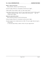
Replacement of Fuses: 

Only the DC output Load and Battery fuses may be replaced. 

Fuse ratings:

 Load fuses 20A max, Battery Fuse 35A max.

Fuse types: 

 32V Automotive Bussmann ATC series or Littelfuse 257 series or equivalent

Page 7 of 11

Issue F

Summary of Contents for ST20-II

Page 1: ...of the load from an external 13 8V DC power source The units are fully enclosed ready for direct wall mounting All connections are at the rear of unit providing convenient wiring and installation Use...

Page 2: ...battery will be charging at 0 8A When the battery voltage is sufficient 10 5V for first power up 11 5V and 11 7V for subsequent reconnection with and without mains respectively the LVD will connect th...

Page 3: ...ll shut down It will attempt to automatically restart every 5 seconds until such case that the fault is removed Fusing Each load circuit and the battery have been fused to provide fault protection and...

Page 4: ...shut down A minimum ventilation of 20 000mm2 to the outside world must be provided CAUTION Do not install unit in same compartment as batteries or flammable material such as petrol Ensure that the ins...

Page 5: ...ating QC connector suitable for cable size Connector pin out is shown below Cabling sizes DC cables must be sized to carry the maximum full load current and not exceed the system volt drop requirement...

Page 6: ...r supply terminal or negative chassis ground If battery is connected to chassis ensure a connection exist from chassis to Batt VE terminal of power supply Battery Disconnection Procedures Battery shou...

Page 7: ...servicing a battery disconnect the power supply Batteries are electrically alive at all times and must be treated with extreme caution They can supply high short circuit currents even if they appear d...

Page 8: ...tion 17V Over Current Protection ST20 II 20A to 25A load battery current ST35 II 35A to 38A load battery current Battery Current Limit 10A 1A ST20 II 15A 1A ST35 II Battery Connect Disconnect Connect...

Page 9: ...A detailed description of the operational requirements for the charging algorithm is described below Present Output Set Voltage Conditions Required to Enter Operational State Operational State New Ou...

Page 10: ...oost charging mode active after resumption of mains input supply set 15 minute boost timer Vboost Vboost No mains input voltage is detected Boost charging mode while no mains is detected Vboost No Mai...

Page 11: ...or devices in close proximity 3m and as such do not guarantee that the power supply will not cause interference with devices such as TV s or radios The ST20 II 35 II have been designed with equipment...

Reviews: